


As usual, WarbirdsNews has received the latest XP-82 Twin Mustang restoration update from Tom Reilly at his workshop in Douglas, Georgia. Here’s what they’ve been up to this month!
August was an incredible month for accomplishments at the XP-82 restoration shop!
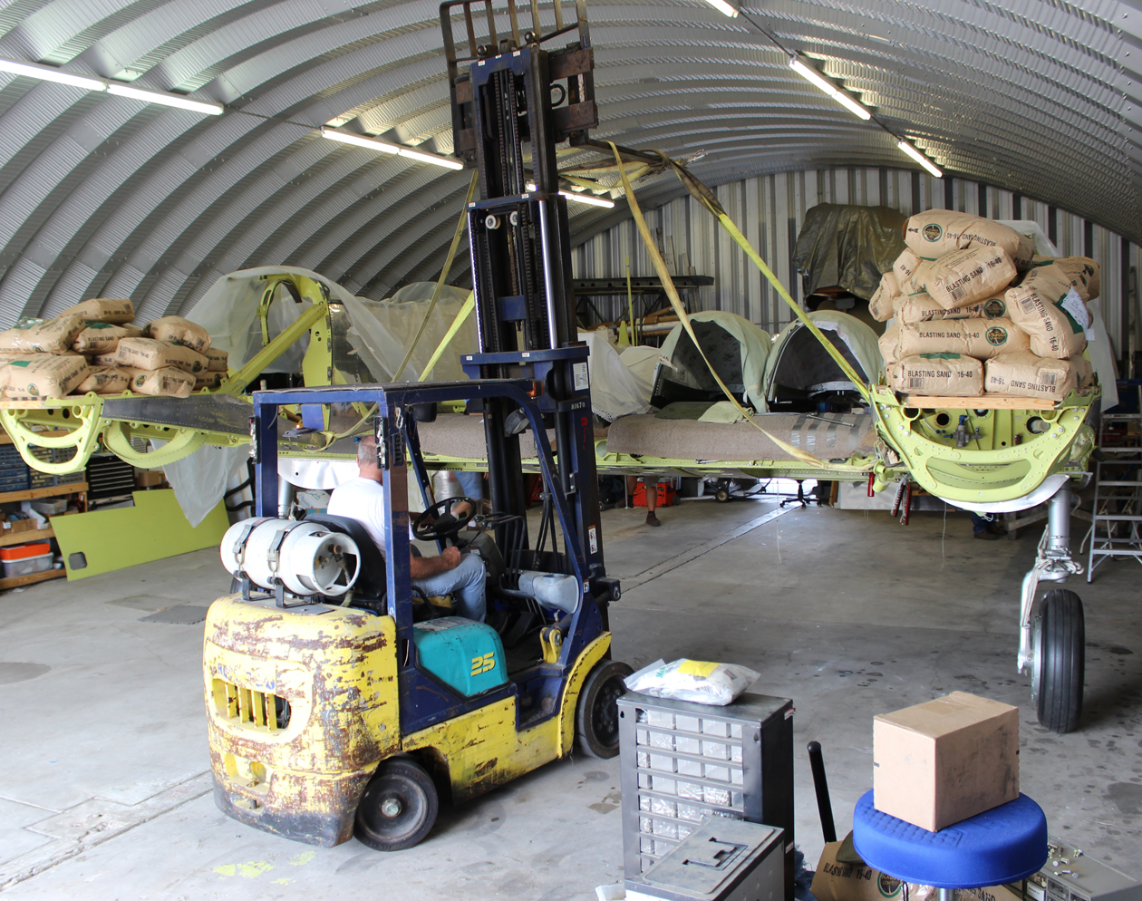
Wings Removed and Fuselages/Center Section Pivoted
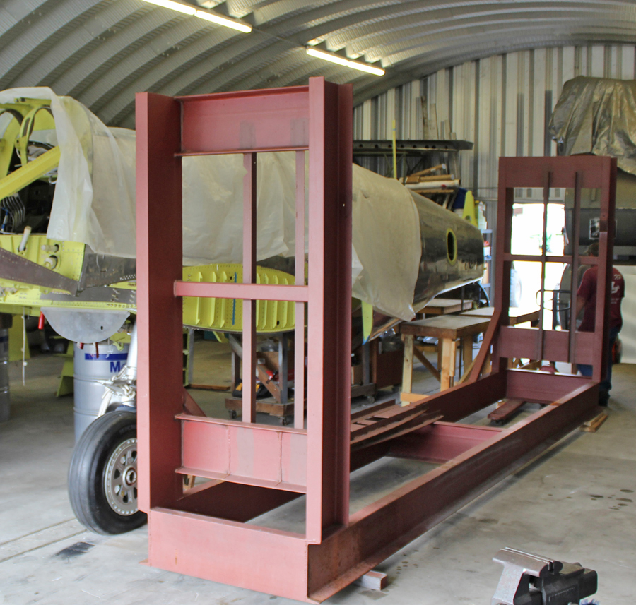
August 15th saw the team turn the fuselages/center section assembly 90º to the south in the hangar. Reilly and his crew hoisted the aircraft using the factory-mounted, 45° lift points on the center section’s inboard sides, right against the fuselage lower longerons. These lift points (¾-16 threaded ports) were designed to bear the weight of the entire aircraft, including engines, so were more than capable of handling the incomplete XP-82. In fact, the team was able to lift the entire, balanced center section with both fuselages and engine mounts with just one man lifting and guiding each rear fuselage. The lift and pivot operation took roughly two hours to reposition the aircraft so it will eventually be able to slide out of the large south-facing hangar door.
After the lift and pivot, Reilly leveled the aircraft in pitch and roll to within 1/30th of one degree, about the thickness of a piece of cellophane. Reilly’s team manufactured two vertical steel support pipes to fit into the rear jack points, immediately forward of the tail wheel attach point. The design allowed them to be vertically adjustable. They also leveled both fuselages on the center section by using the factory shims. They then set about the process of finally attaching the fuselages to the center section longerons with the remaining six of twenty internal wrenching NASA bolts. (Longerons are the main beams that are the lower structural rails mounted in the bottom of both fuselages.)
Verticals, Horizontal and Rear Fuselage Extensions
The following day the team installed all of trim actuators in each vertical and the horizontal, (three) and installed all the trim cable pulleys in each vertical.
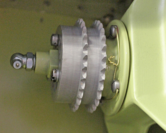
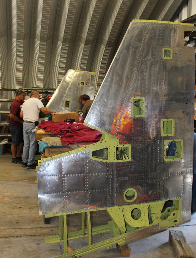
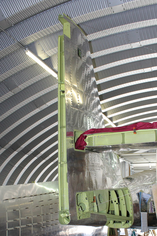
Reilly’s team then attached each vertical to its respective side of the horizontal stabilizer. They had to align and hold the verticals in a perfect 90º position in relation to the horizontal stabilizer. To achieve this, they used diagonal wires with turnbuckles to make the final tiny adjustments as the verticals are permanently held in place when the aft fuselages are high-shear riveted and bolted to the forward fuselages. A few days later, the team built a temporary cushioned wooden scaffold, and lifted the horizontal/verticals/aft fuselage sections up and forward to within ½” of their final attachment positions.
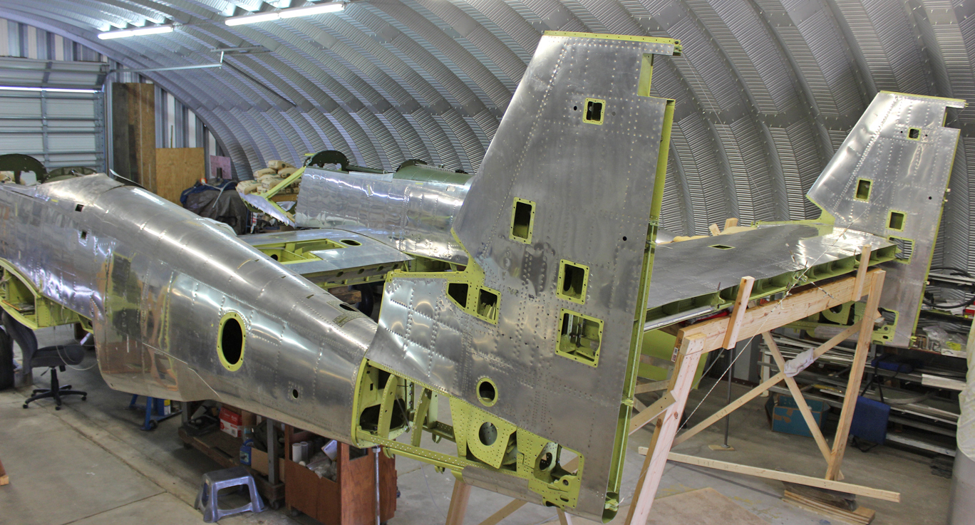
Then came all of the final adjustments to make sure everything was properly aligned prior to drilling and reaming any of the attach holes for the fittings. There were eight exact measurements that had to be aligned:
1. The angle of incidence (the pitch up and down on the horizontal stabilizer in relation to the center section).
2. The alignment of the two vertical stabilizers (toe in, toe out).
3. The exact vertical measurements on the verticals in relation to the horizontal measured between the two top and two bottom rudder hinge points horizontally and diagonally.
4. The exact forward and aft dimension of the center section trailing edge to the leading edge of the horizontal stabilizer.
5. The left and right measurements on the aft fuselage extensions to the forward fuselages. This exact measurement is obtained by shaving the attach fittings of the horizontal stabilizer to the vertical stabilizer. We intentionally machined all four of them 1/32” thicker to give us extra material if we needed to make small adjustments.
6. The twist of both aft fuselage extensions to align the upper and lower attach points.
7. The vertical attachment of the aft fuselage extensions to the forward fuselage attach points.
8. The alignment of the dorsal fins with the leading edge of the vertical stabilizers.
Everything lined up perfectly. So then the team started final drilling and reaming all the attachment hardware for the high shear rivets.
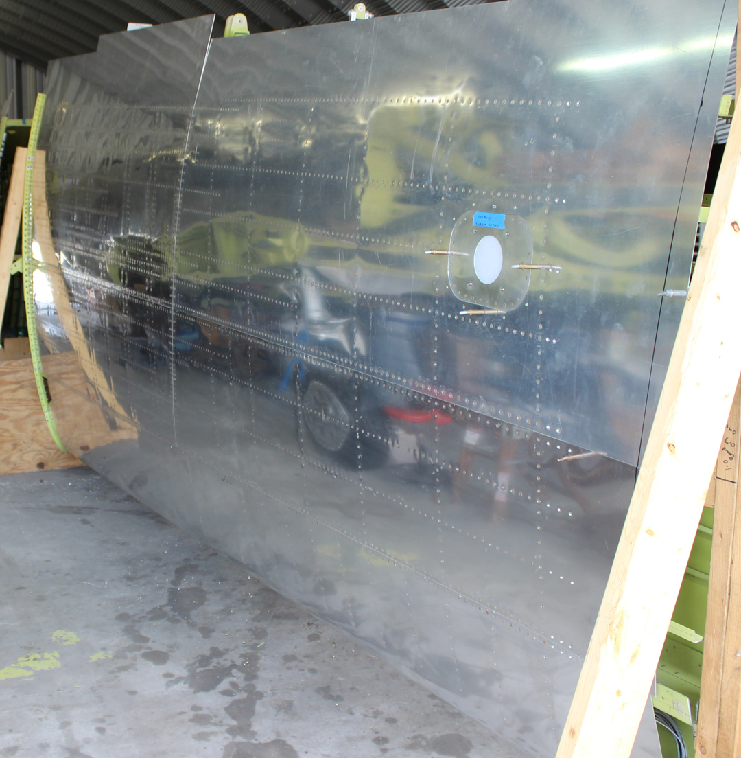
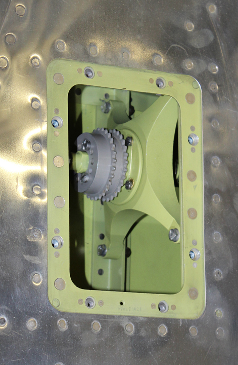
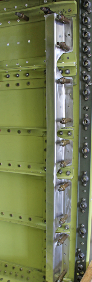
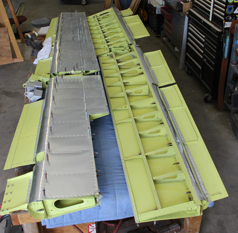
Outboard Wings and Center Section
The restoration team completed riveting all of the outer wing panel top skins in place while the wings were still mounted on the fixture, along with one more bottom skin for each wing; locking the wings into their final shape.
Both wings are now off the fixture, and the team is completing the final riveting, and finishing the fuel cell stand-off angles.
Two of the restoration team members are fitting and installing the new aileron attach hinge point fittings. One of contract machine shops is making the final two outboard flap hinges.
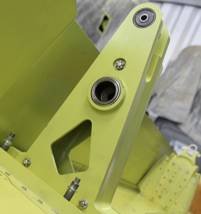
The new inner and center aileron attach hinge point fittings are presently being installed on both wings.
The final Adel clamping of the wiring harnesses in the center section is now close to completion along with the final attachment of the three wiring terminal strips in each wheel well. One of the project’s volunteers is sewing the canvas covers that shield and protect these wiring bundles and terminal strips from dirt and moisture thrown up by the rotating tires when the wheels are in operation. The center section nut-plate channels that attach the fuel tank close-out panels between the outboard wing and center section are also now finished.

And that’s all for this month. Many thanks again to Tom Reilly for the update! You can learn more about the project on their blog HERE. Please be sure to check back with WarbirdsNews in early September for the next installation following the XP-82′s road to recovery!
Please click HERE for some of our previous updates.
Be the first to comment
Graphic Design, Branding and Aviation Art