
")

“Time flies,” as they say, and hot on the heals of our January XP-82 restoration project update, Warbirds News now has the goods on what Tom Reilly and his team have been up to with their Twin Mustang prototype in February. This update is based upon Tom’s words. Go beyond the jump to read the details, and see the fascinating images of true craftsmanship.
Outboard Wings
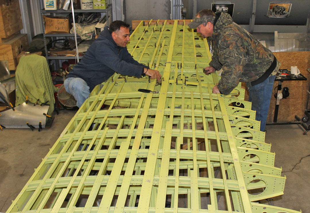
Ayman, Tim, Paiden and Josh have completed all of the preliminary rib-to-stringer-to-spar drill-ups on the left-hand wing. They made all of the preliminary drill-ups with a reduced-size bit to allow a small amount of alignment adjustment, if needed, once the wings are in the assembly fixture.
Paul and Randall have completed the final preliminary drill-up of the right-hand outboard wing and are now fitting the two leading edge skins.
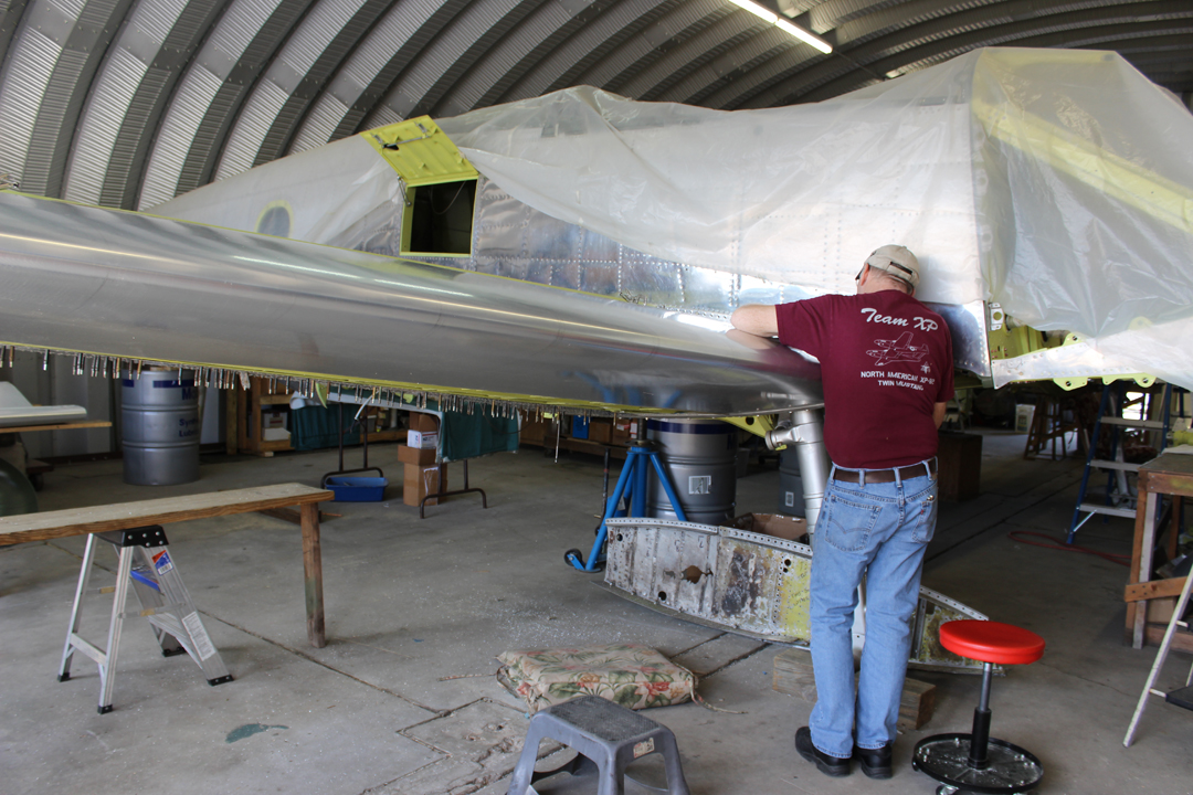
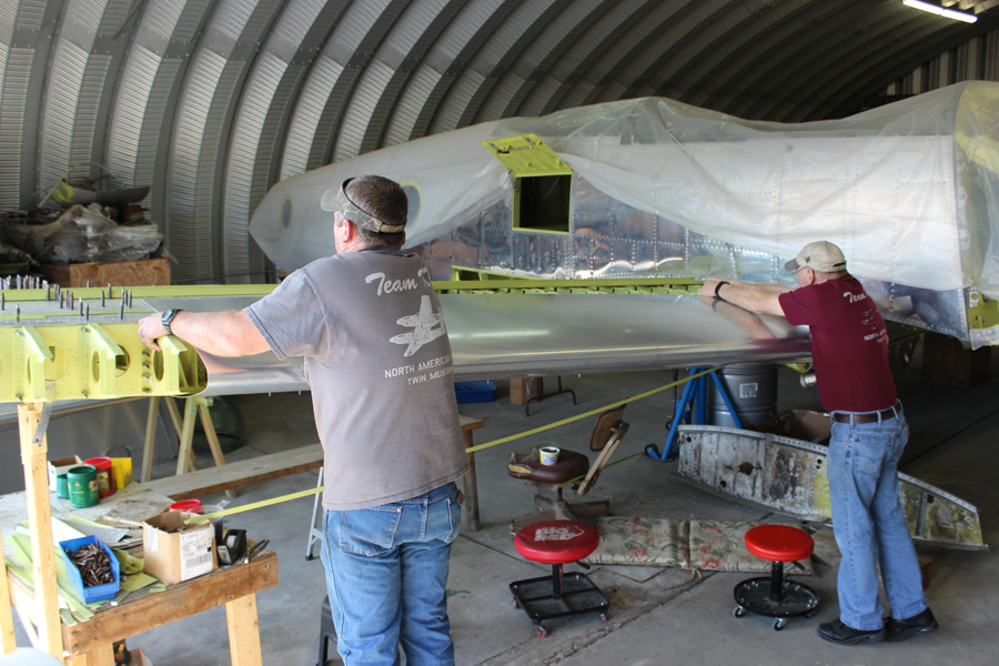
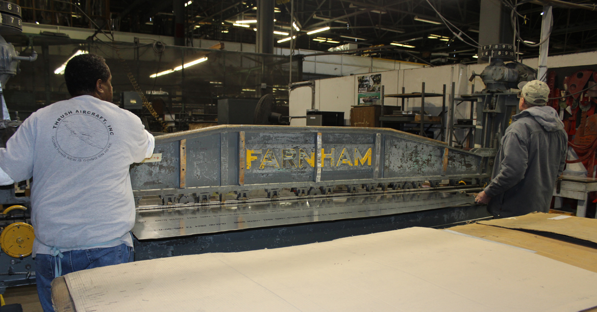
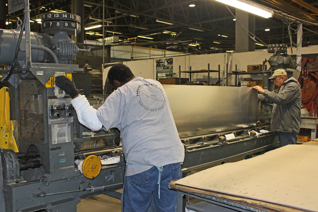
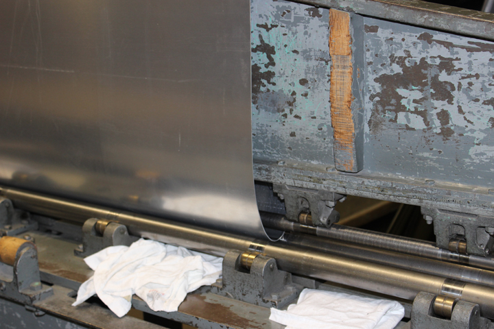
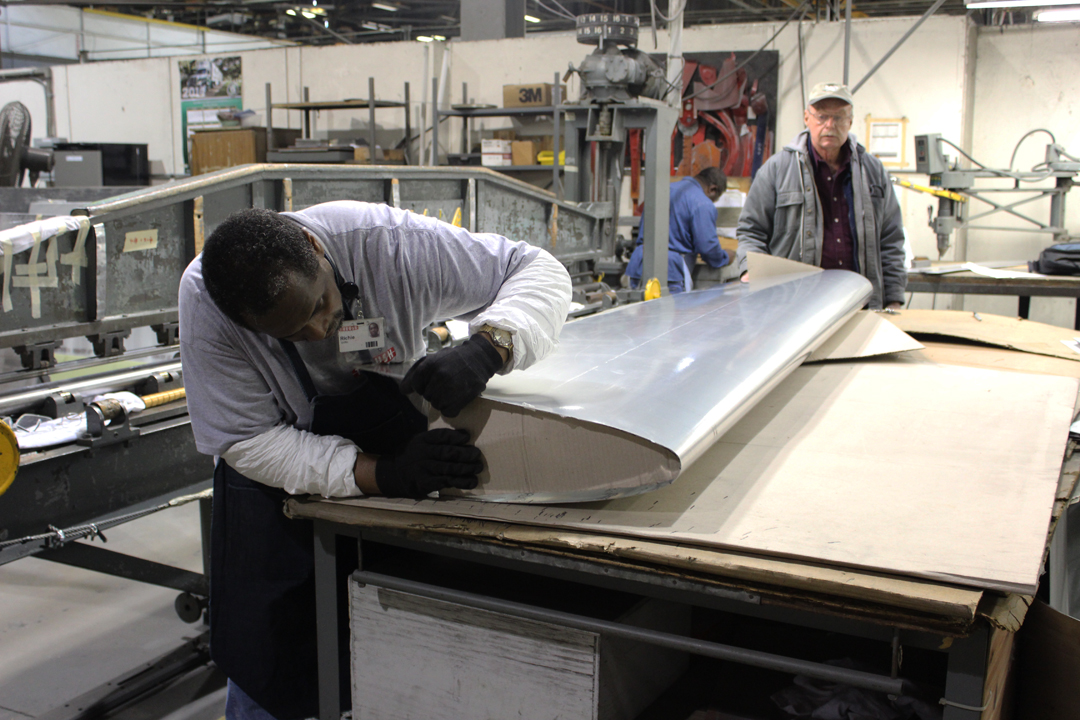
Wing Leading Edges
Weezie and Tom went to Thrust Aircraft in Albany, GA, to have the leading edges rolled on their Farnham roller, a special roller that will simultaneously roll two different leading edge curvatures on each pair of skins for each wing.
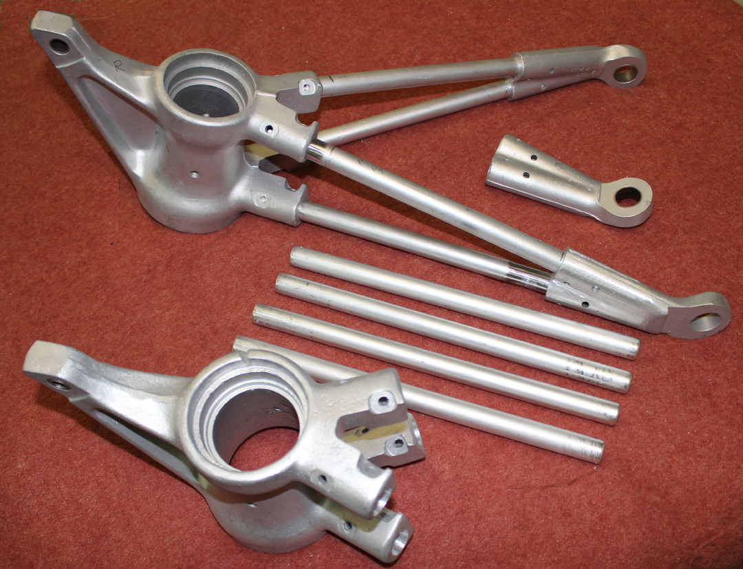
Aileron Controls and Fittings (Boosted / Non-boosted)
The XP-82 prototype came with non-hydraulic boosted aileron and elevator controls, unlike all subsequent B through H production models. The boosted controls assist with taking the control forces off of the pilot’s stick when the air speeds start getting up in the 400+ mph range. The Twin Mustang parts purchased from Alaska all had boosted aileron control fittings in the wings and ailerons. Tom’s team were able to save all four fittings (two hinge and two control) required in the four ailerons to use with the non-boosted XP system. (The two outboard ailerons do not require any individual aileron controls as they are both mechanically linked to the inboard ailerons.) The team are machining the non-boosted bellcranks and associated cable sectors required in both wings and these should be completed within a couple of months.
Center Section Fuel System
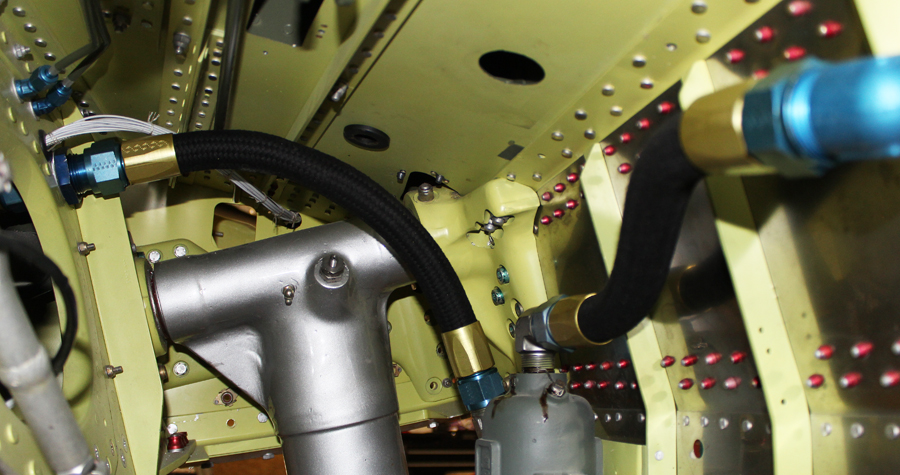
Tom completed the fuel feed lines that run from the fuel shut-offs through the wheel-wells to the C-4 strainers, and then through a pair of fittings on each firewall to the engine-driven fuel pumps. He chose to use the later model Stratoflex 111 hose and 300 fittings due to their fire resistant construction. The original hose and fittings were a Mil-H 6000 non-reinforced hose with pushon nipple fittings that were not at all fire resistant. This is a safety improvement that Tom chose to do, but this modification could easily be changed back to the original style if desired for originality.
Machine Work
The sub-contractor machine shops are making excellent progress on the last number of items that needed for the center section and wings. Martin Radiator is also making good progress on the two heat exchangers.
Floorboards
The phenolic/carbon fiber floorboards are under manufacture in Florida using the molds Tom’s team made.
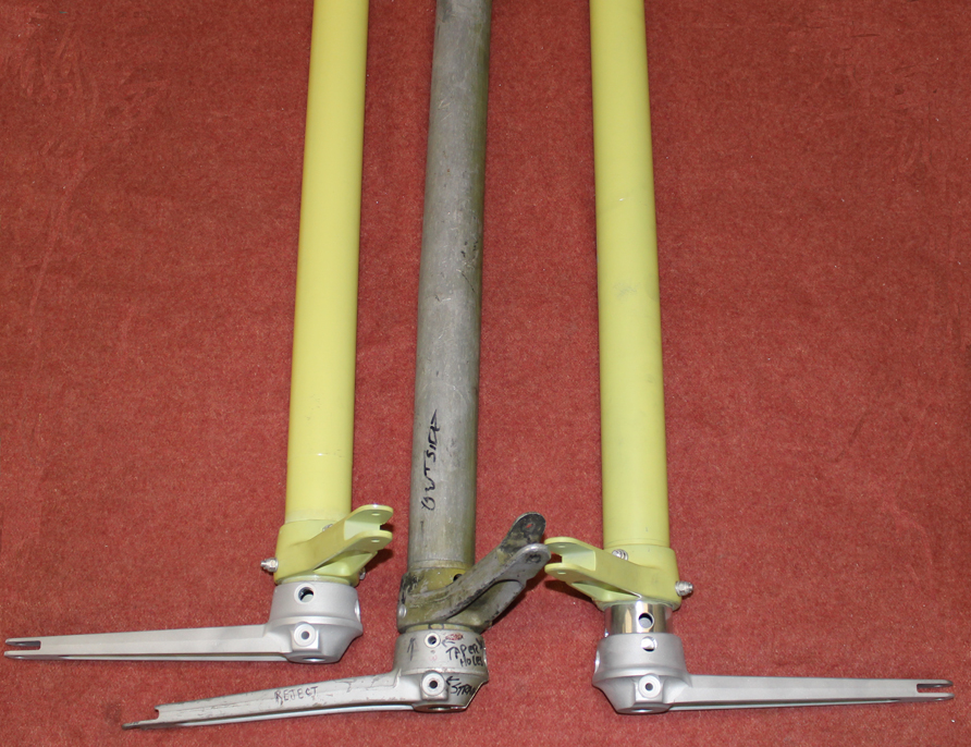
Tail Wheel Assemblies
The two tail wheel assemblies have passed NDI inspection. Tom built eight new 4130 steel tube mounting arms as the originals were rusted due to being in the weather for years. Although two of the four mounting lugs passed NDI inspection, Tom chose to have them re-machined due to some deep scratches. The only other tail wheel parts still requiring manufacture are the two yokes which hold the tail wheel, and the four small tail wheel gear doors as the originals were all severely corroded.
Push-Pull Control Rods
While in Florida having the tail wheel parts inspected, Tom had his welder extraordinaire in Titusville weld up many of the control rod ends to new 4130 steel tubing.
Additional Restored Components
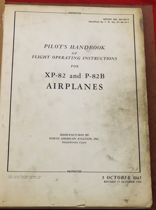
What A Find!
A group from LaGrange, GA flew in to look at the XP-82 project in February. While they were there, one of the men, James Mackey, contributed an original Twin Mustang Flight Manual that had the serial number of Tom’s XP-82 penciled in on the first page. Mackey told Tom that he acquired the manual from a fellow who was stationed at NACA Lewis in Cleveland, Ohio where the XP-82 was based during flight trials. What a find!
Many thanks to Tom Reilly for contributing this month’s project update. Please visit www.xp-82twinmustangproject.com to learn more.

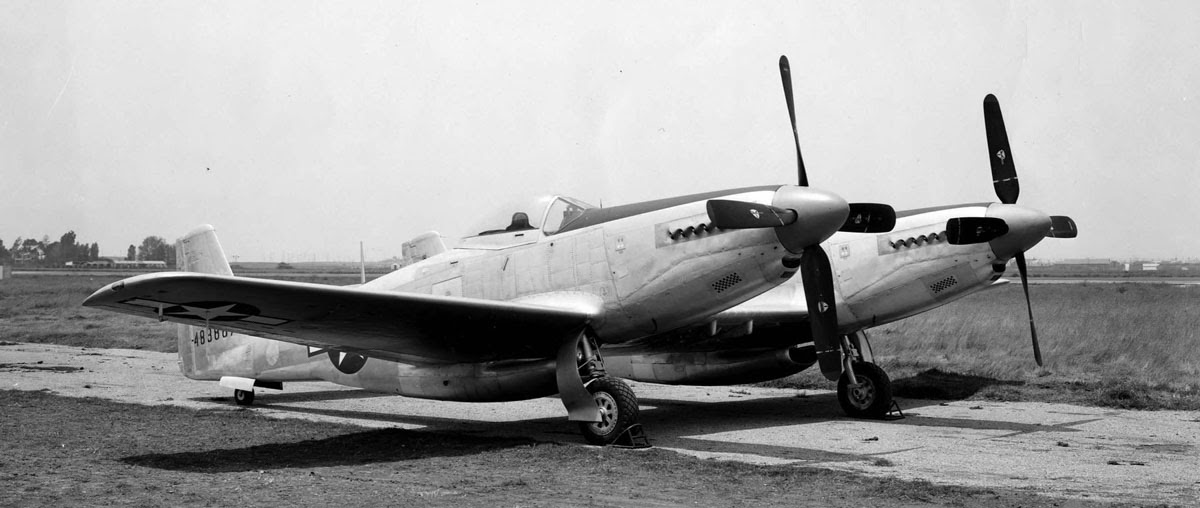
The Mustang P-51D was one and still is one of the most beautiful aircraft ever built. The Twin-Mustang was another along with the P-38 Lightning. These two aircraft were to be used in extreme long range and did their jobs well. Thanks for restoring this aircraft.
This is all so very, very cool!!! Congratulations on what you are all doing to bring your Twin Mustang back to life! God bless!
Beautiful restoration. ..flew p51’s