


Massive Trove of Original NAA Aircraft Drawings Saved!
by Richard Mallory Allnutt (Editor)
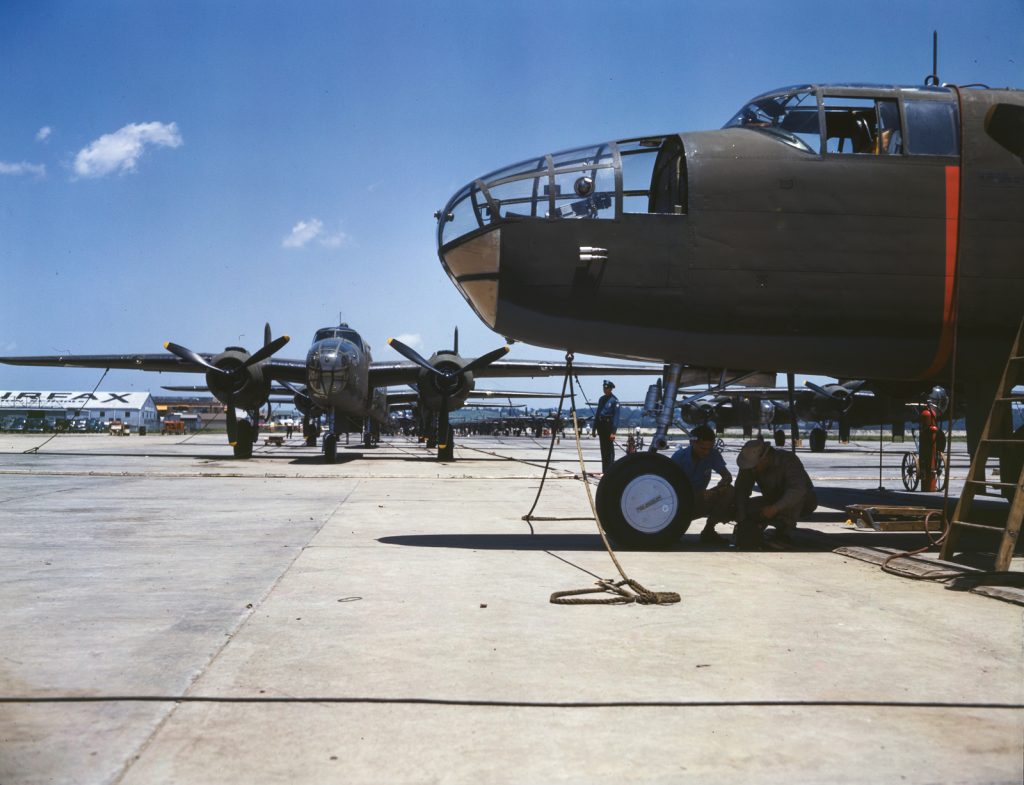
AirCorps Aviation of Bemidji, Minnesota has just announced that they have acquired a massive trove of original manufacturing drawings for North American Aviation (NAA) covering types such as the P-51, T-6, B-25 and P-82. This is a remarkable development, and all due to a lone engineer at NAA named Ken Jungeberg who had the foresight to save these drawings when they were days away from destruction at North American’s plant in Columbus, Ohio during the late 1980s. But before we discuss this find, it is perhaps first worth reflecting upon what it represents…
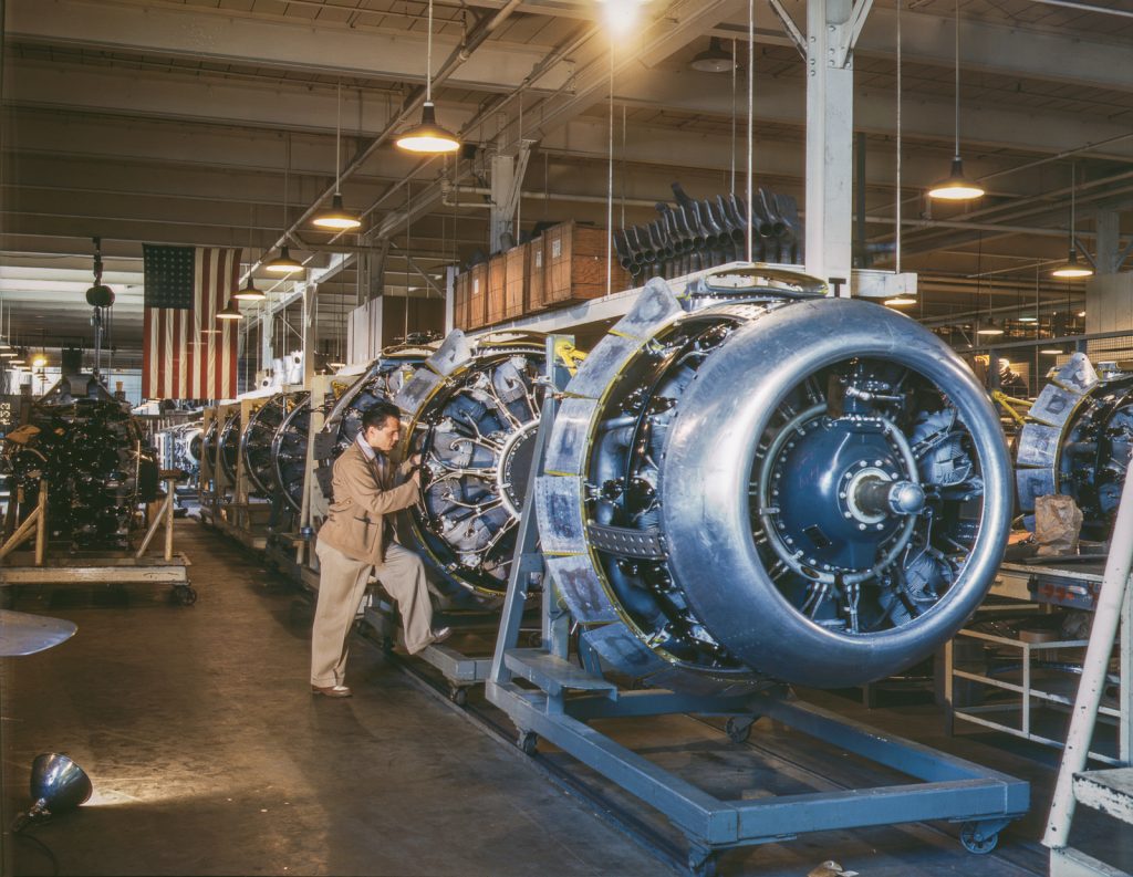
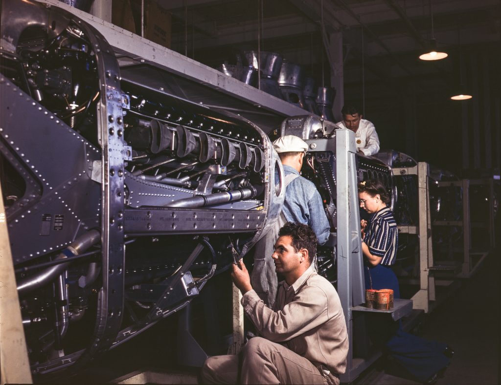
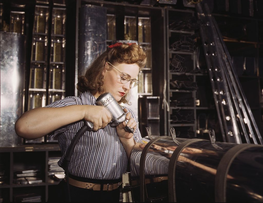
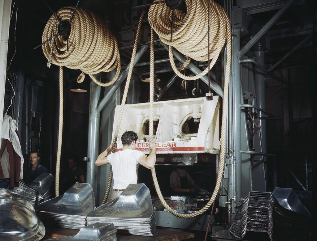
The American aircraft industry produced just under 300,000 aircraft between 1940 and 1945, a staggering feat by any measure, especially considering that just 3,600 rolled off U.S. assembly lines during the entirety of 1940. While aviation companies such as Boeing, Douglas, Curtiss and their like would design the aircraft, and put them together at their factories, it was simply impossible for them to both make all of the components and subassemblies on site and keep up with production demand. They had to subcontract out the bulk of this work once a design received an order for full-scale production. Indeed, much of America’s entire manufacturing base was involved in this effort – from small ma and pa furniture shops to industrial giants like Ford and Chrysler – whether they were making map cases or wing panels. Some companies, such as Ford, even had their own aircraft assembly lines, like the one in Willow Run, Michigan which built B-24 Liberators.

But have you ever wondered how it was possible to have such a prolific output of high quality aerial machinery when each aircraft assembly line received component parts from so many different independent subcontractors? How was it possible for all of those many thousands of parts to fit together properly in such a repeatable fashion?
The answer is pretty simple; it all came down to the quality of the manufacturing drawings which the aircraft company engineers created during their design process. If you had a coherent set of accurate drawings showing how to make each part, and how to put each assembly together, then you could rely upon skilled workers at disparate factory locations to produce components whose dimensions complied with design tolerances. Of course, there were times when problems arose, but when they did, the engineers usually found solutions. But a coherent set of manufacturing drawings was key to this effort.
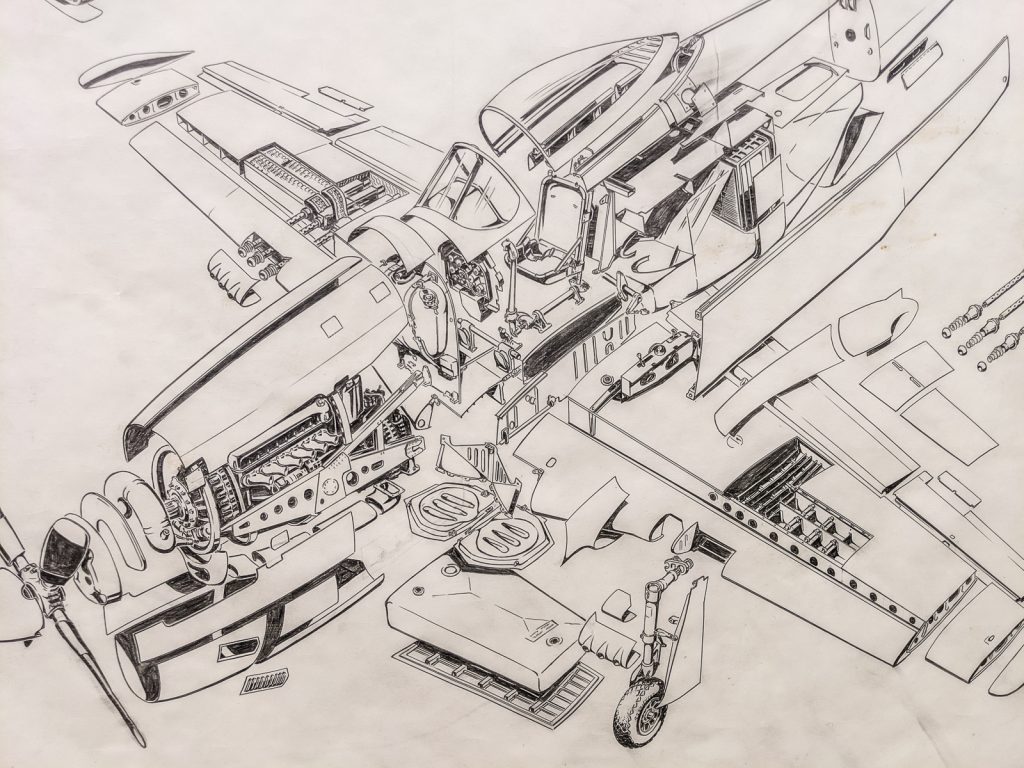
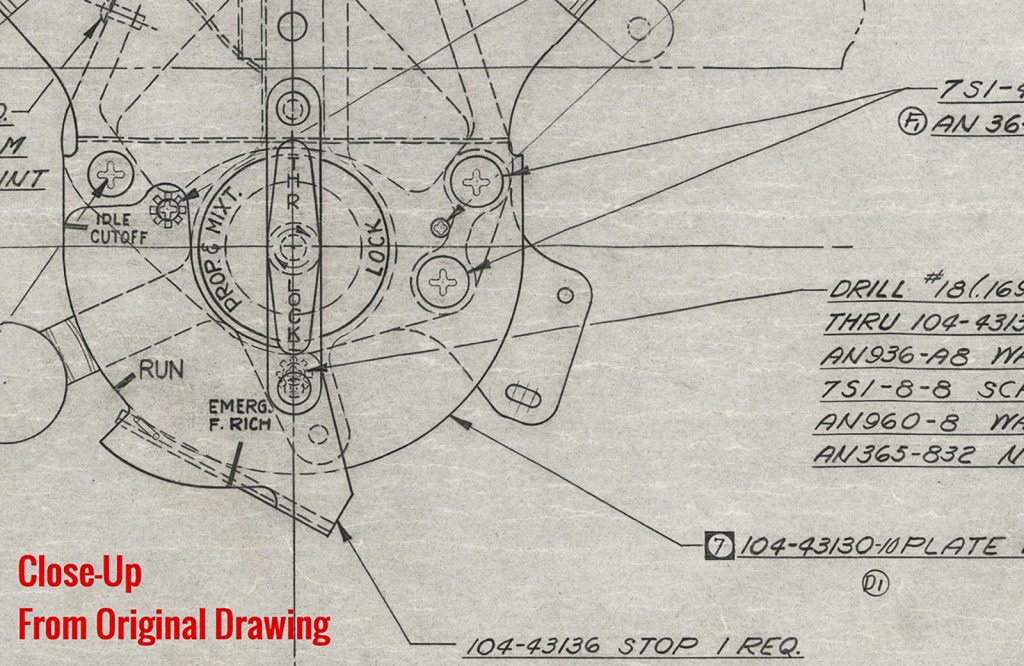
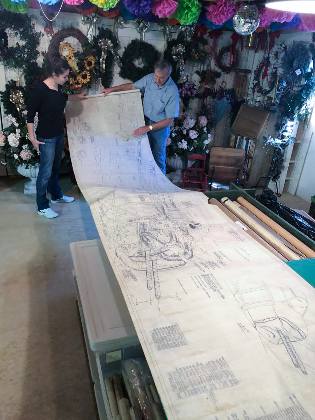
However, every single component, from the tiniest rivet to the entire aircraft, required drawings to properly describe them. Obviously, the more complex parts and sub-assemblies required multiple drawings, sometimes hundreds. Highly skilled draftsmen and women created all of these drawings by hand by – usually using pencil on vellum drafting paper. Drawings could sometimes be massive too, extending ten feet or more. The finished product was designed to be practical, fully describing the part and how it fit into an assembly. Drawings were often exquisitely beautiful too – more works of art than simply functional.
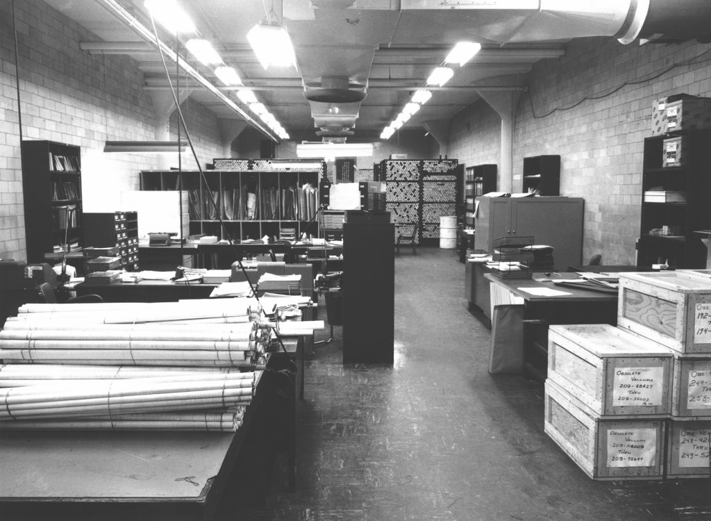
As an aircraft design evolved though, the set of drawings had to evolve as well, leading to many new drawings for the updated parts and assemblies. As you can imagine, given the vast number of drawings involved, simply finding room to store them became an issue, and costly too – especially once a design became obsolete and went out of service. Warehousing these drawings began to require significant resources, and as the aircraft industry consolidated, parent companies often disregarded the distant heritage of their newly-acquired assets. Drawings for old designs held nothing more than historical value, and cost money to keep. So the bean counters usually had their way, and simply dumped, shredded or burned these documents – documents that feel priceless today for those of us with a passion for aviation history, and doubly so to those among us who restore old planes.
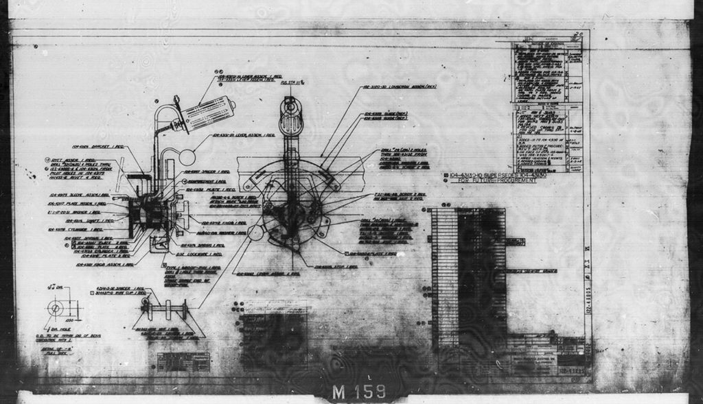
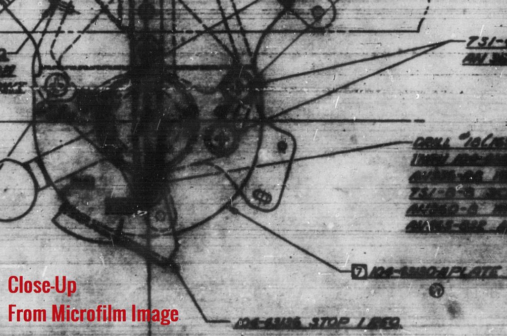
For the most part, all we are left with today are a small subset of the original drawings recorded on 35mm microfilm, but even this is a pale representation of what an original set of drawings would have entailed; these microfilmed drawings can be hard to read due to the often poor quality of their original photographic capture. But that is what we have left for the most part, and until relatively recently, if you wanted a set of drawings for an American-made aircraft of WWII vintage, the only real option was to contact the Smithsonian’s Air & Space Museum and hope that they had what you needed – and then pay a small fortune for the reproduction of the appropriate microfilm. But even the microfilm has its problems, as drawings are not stored in order, or by sequence, so you might have to search across five or six different rolls of microfilm just to find the drawings for a handful of parts in an assembly, and even more if you need to find the specific version of a part. It is a tedious and time-consuming process!
But then along came AirCorps Aviation with their AirCorps Library project. For a small annual subscription of just $50, you have access to serious engineering details, including manuals, for several dozen American WWII-era aircraft designs. They have also digitized the engineering drawings for a number of these aircraft too, such as the P-51 Mustang, F4U Corsair and B-17 Flying Fortress. While they haven’t digitized everything available yet for each aircraft design – it’s a massive process – it is a fascinating resource for anyone with even a passing interest in WWII aviation. It is easy to search for the drawings you need, and they have taken the time to compile their database efficiently, so that every available drawing for a specific part number is neatly stacked in the order it was drawn, making it so much easier to find the correct version of the part you need. You can easily zoom in and out of a drawing too, so you can read the finer print with greater comfort and certainty. Speaking as someone who has actually used these drawings to create 3D CAD renditions for restoration projects though, it has been invaluable to my efforts, and well worth the small entry price. Even so, the available sets of microfilmed drawings are incomplete, and often have illegible data…
This is why the news about the preservation of more than 15,000 original drawings produced by North American Aviation that relate to such iconic designs as the T-6 Texan, P-51 Mustang and B-25 Mitchell is such a revelation. AirCorps Aviation has gained access to these drawings, and is presently cataloguing and copying them for their subscription library. However, the fact that these drawing still exist at all is down to the dedicated efforts of just one man, Ken Jungeberg. His name will resonate in aviation lore for generations to come due to his foresight in saving such historically important documents. For further details on this remarkable news, we will let AirCorps Aviation’s Ester Aube continue the story…
The Ken Jungeberg Collection:
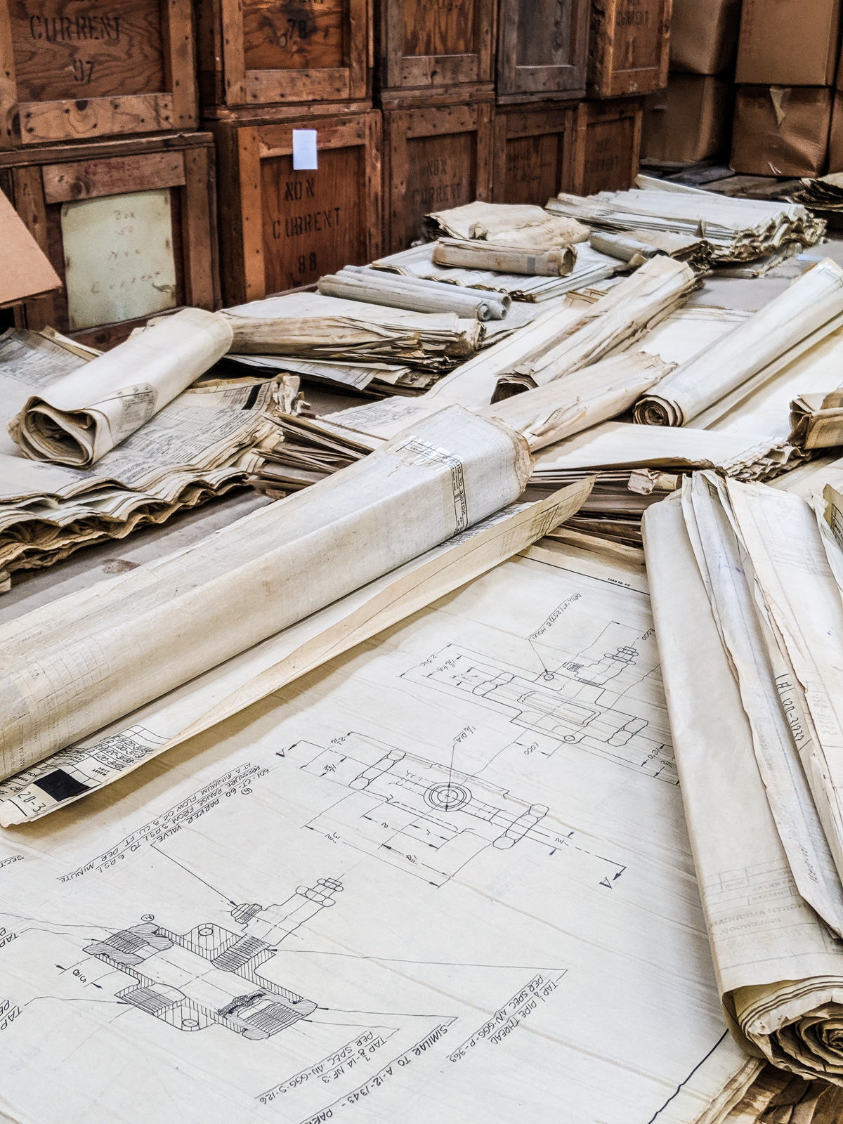
AirCorps Aviation announced today that they have acquired a collection of original North American Aviation engineering drawings. These drawings, part of the newly named Ken Jungeberg Collection were stored in the archives of North American’s Columbus, OH factory until 1988. Each drawing is hand-drawn in pencil on tracing vellum, and was used to develop and build the P-51, B-25, T-6, P-82, and many more.
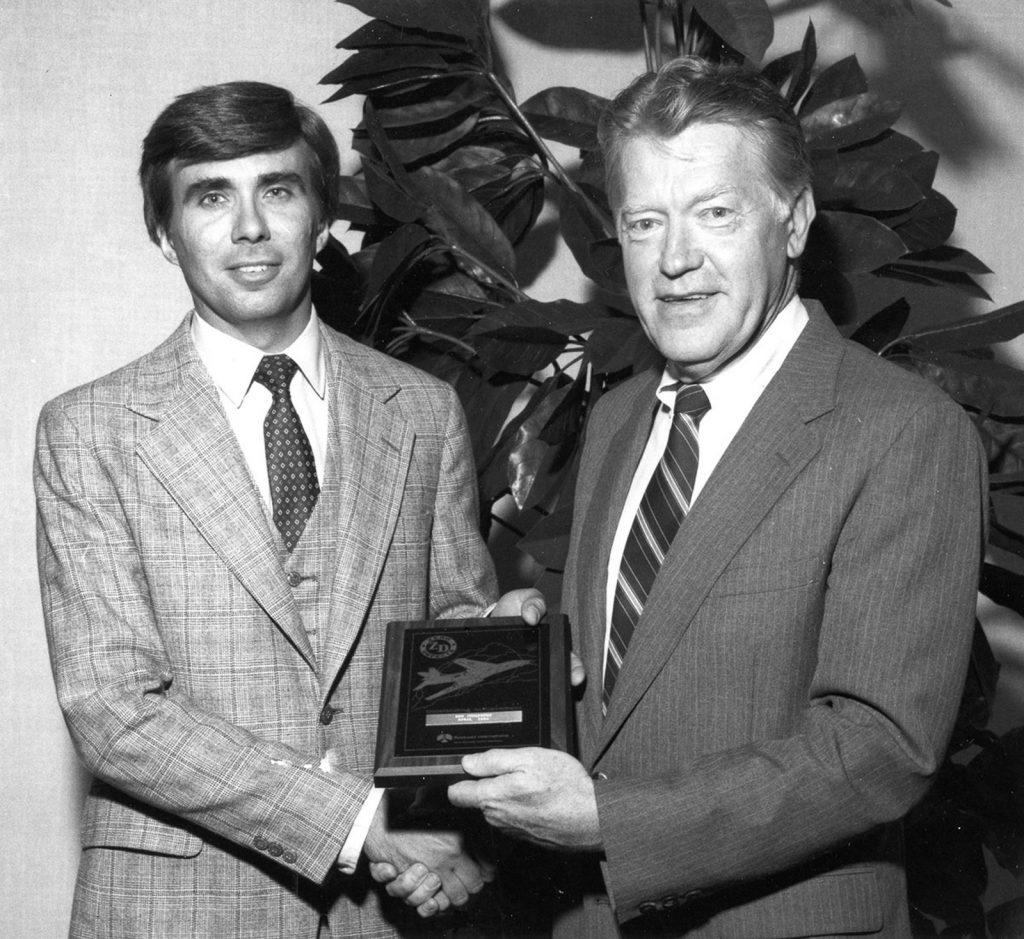
Ken Jungeberg was the head of the Master Dimensions department at Columbus in 1988 when the factory closed its doors. When he heard that North American was planning to burn all the WWII era drawings in their archive, he knew he had to do something. He began writing letters and making calls to his superiors, advocating to save the drawings. Discouraged by responses that there was nothing he could do, Ken had all but given up, until a twist of fate changed everything.
A situation that would have been a tragedy under normal circumstances turned positive when a pipe burst in the archive room that stored the drawings to be destroyed. The room all but filled with water, cracking the cement foundation, and soaking the contents of the room. North American employees emptied the room, and piled the soaking wet drawings in a heap on the factory floor, where they sat for the next two weeks.
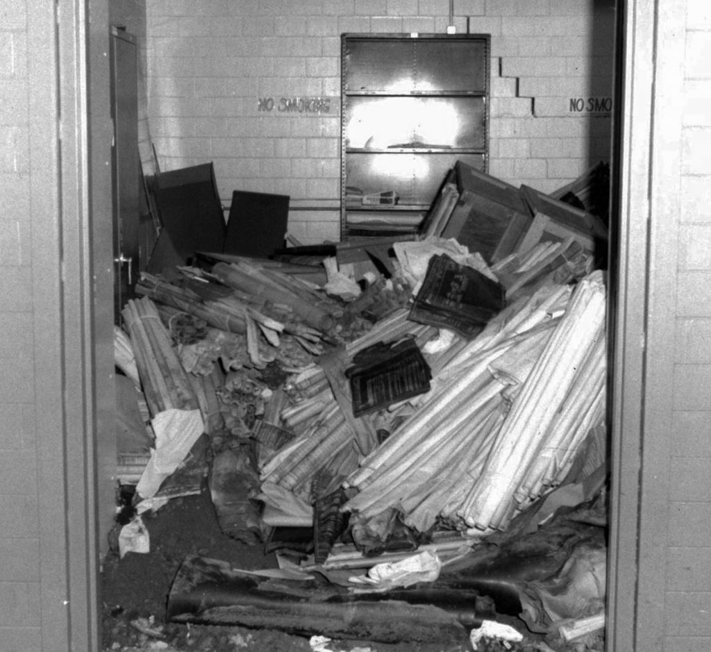
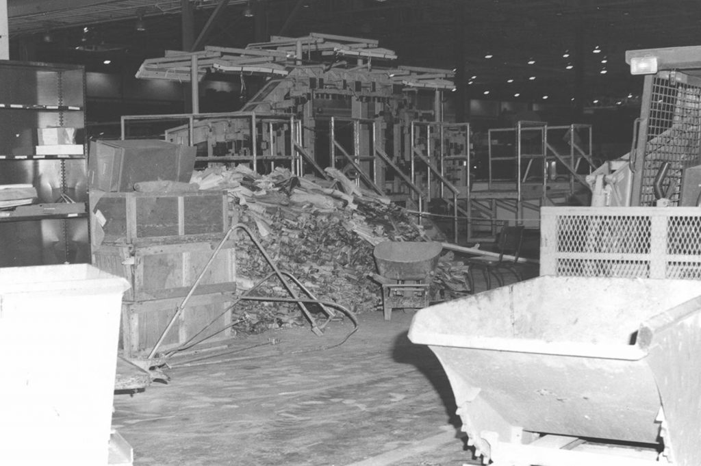
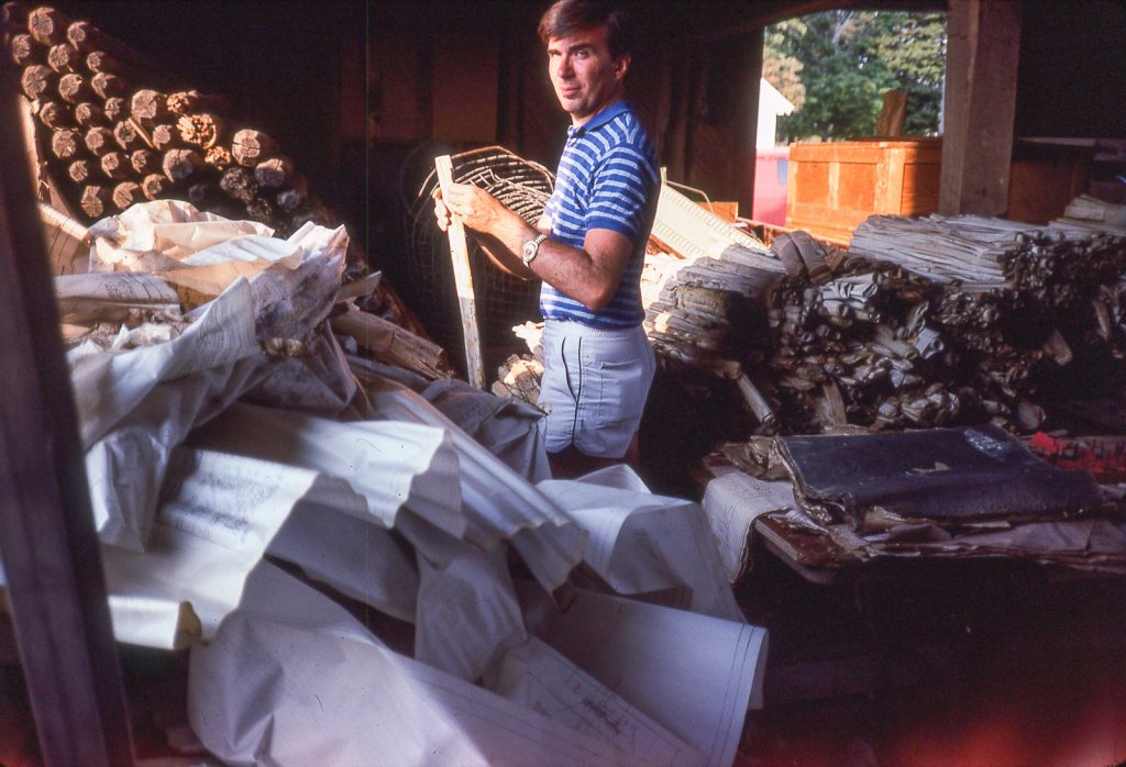
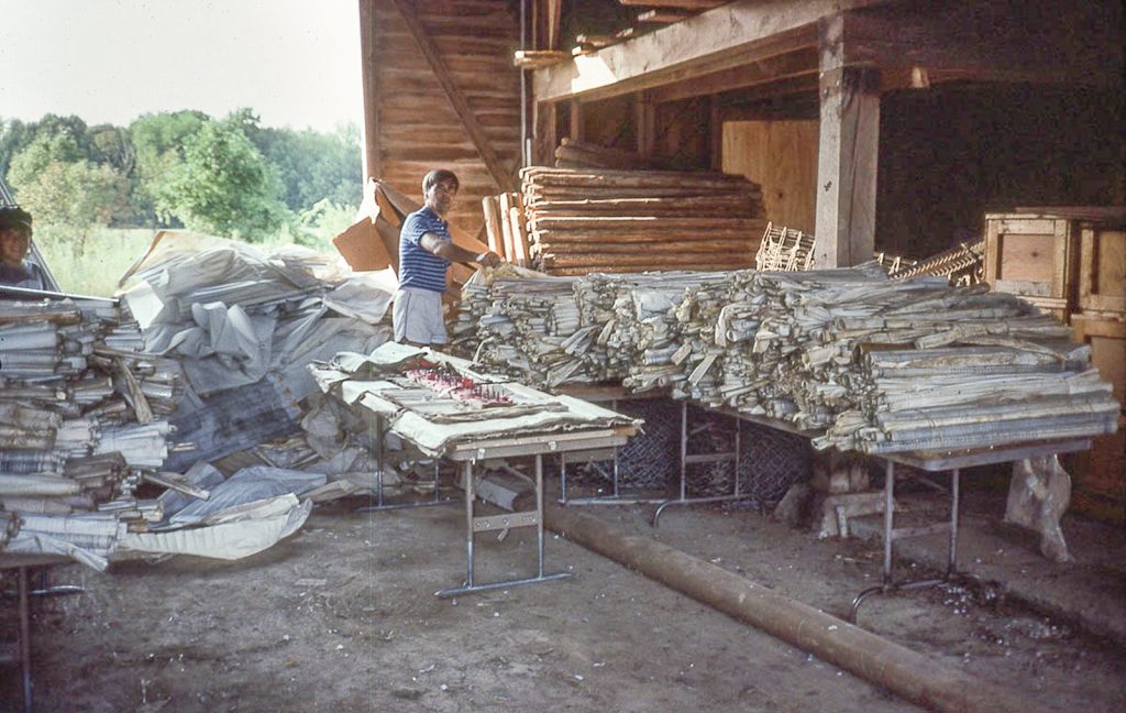
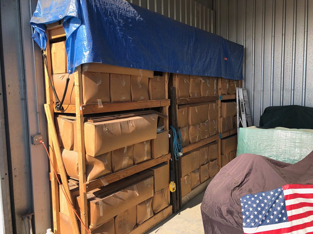
It was at the end of these two weeks that Ken got the call he had been waiting for. He was told that he could have the drawings, if he came to pick them up immediately, and promised that they would never end up “blowing around in a landfill”. Clearly the company was still concerned with preserving the name and reputation that North American was known for. Ken rented a truck and he and several friends loaded the drawings, and took them to a barn where Ken began the monumental task of laying them out to dry. Because the drawings were done in pencil on tracing vellum (a very durable media), the information was essentially undamaged.
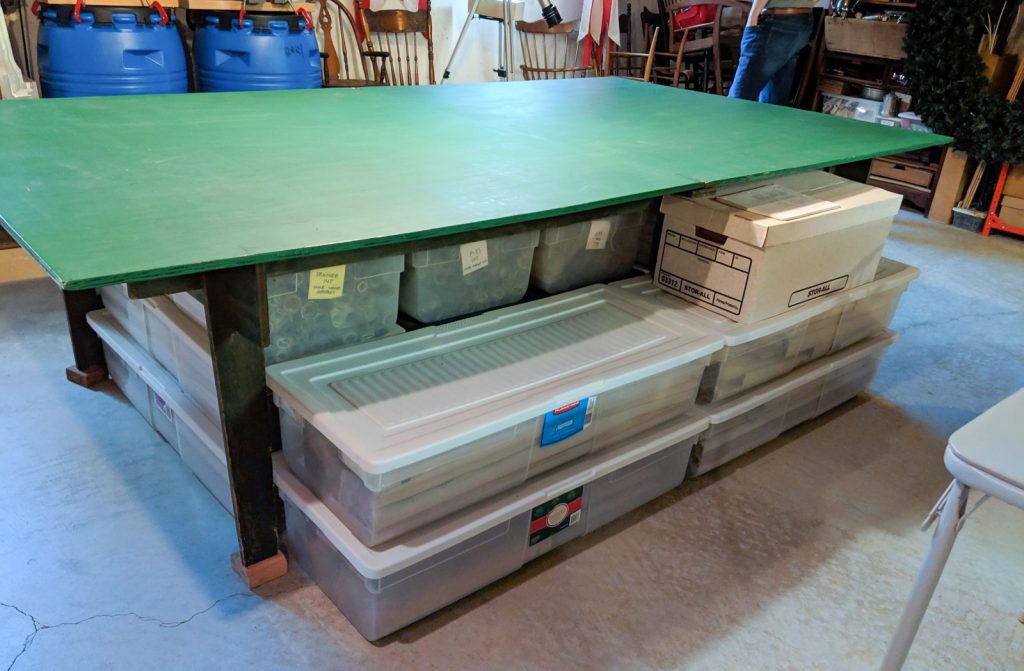
Once the drawings were dry enough, Ken sorted, re-rolled, and boxed them up. He took many to his home, and stored the rest at his hangar at the Warren County Airport in Lebanon, OH. The drawings would remain in this same location for the next 32 years, until 2019.

AirCorps Aviation learned of Ken’s collection in the spring of 2019, and in December of that year Ken agreed to transfer ownership to AirCorps. As the new custodian of this important collection of drawings, AirCorps plans to catalog and organize the drawings so they can be used by the vintage and legacy aviation industry for the first time in history. “These drawings are going to change what we know about the amazing aircraft that North American manufactured during World War II,” says Erik Hokuf, general manager of AirCorps Aviation.
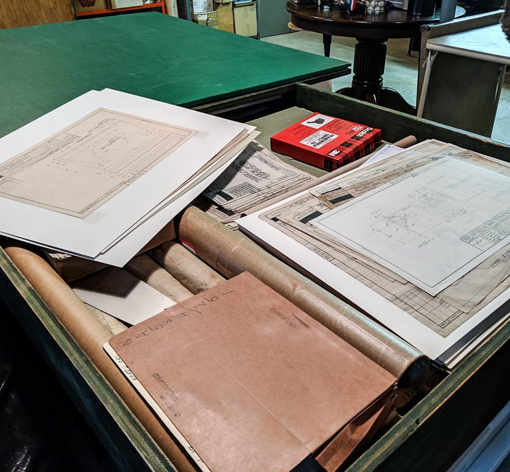
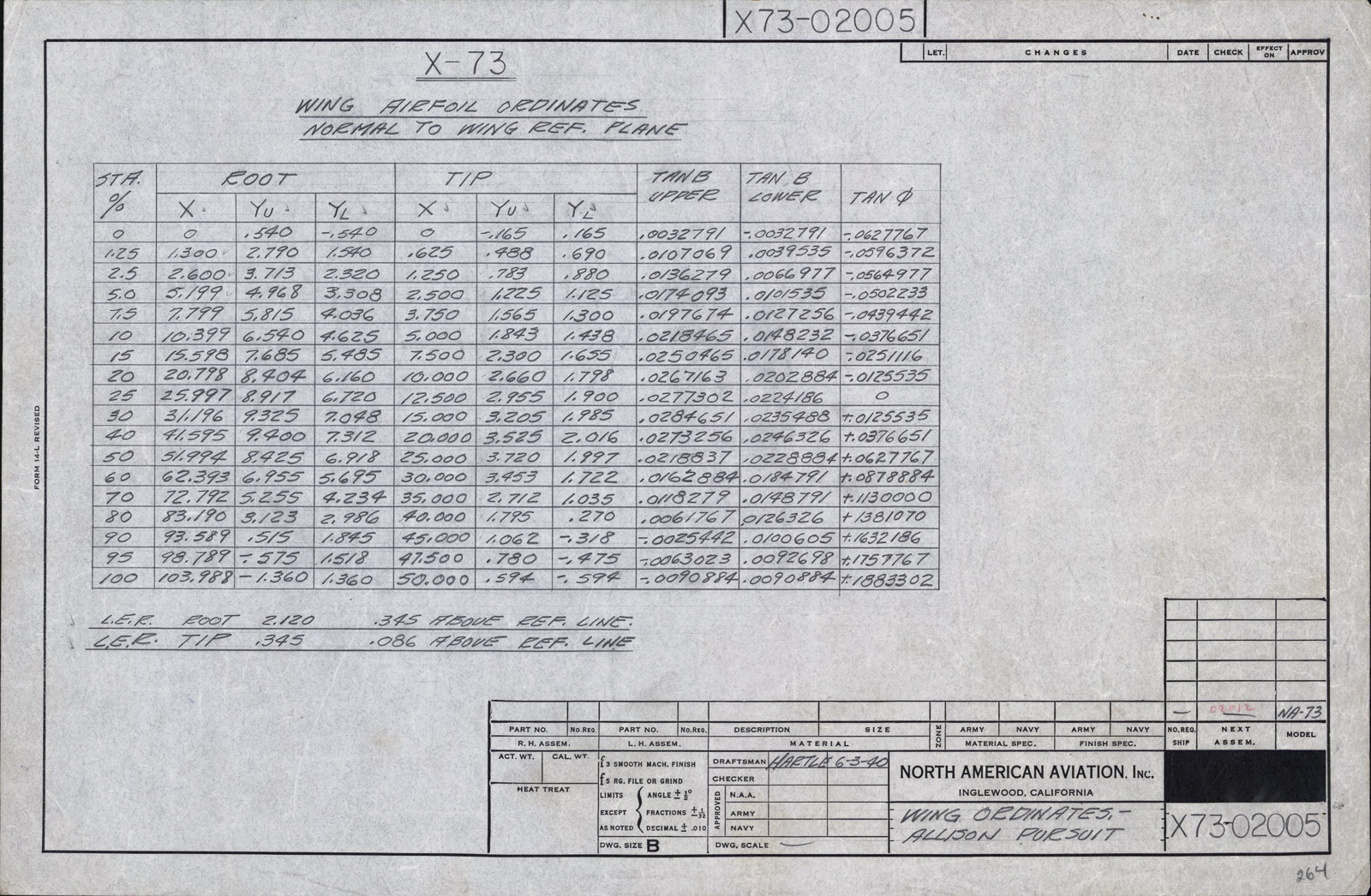
While microfilm and copies of aircraft drawings from this era are not uncommon, few individuals have ever seen a hand-drawn original. The drawings in Ken’s collection largely represent production drawings, and the experimental work that North American’s draftsmen created while developing parts and assemblies that would later be finalized. A perfect example being the drawings distinguished with the prefix 73X. These drawings were used to develop the widely popular P-51 Mustang in just 120 days in 1940, and have never been seen by the general public.
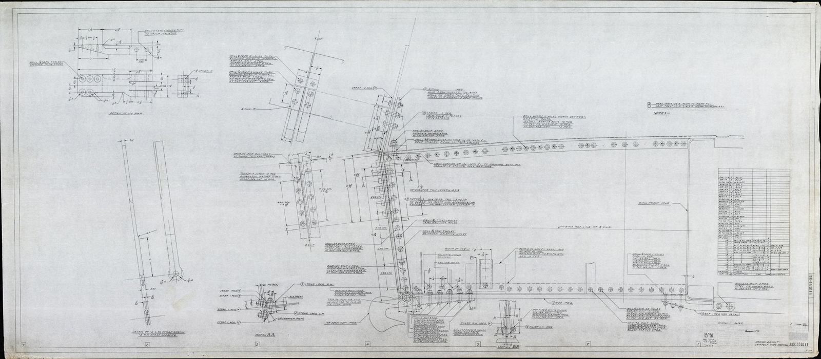
Another exciting example of the experimental work being done, is a tailhook drawing for the P-51. It has been speculated that North American was thinking of modifying the Mustang for use on aircraft carriers, and drawing 109-955033 titled Design Layout – Catapult Hook Install proves that this was true.
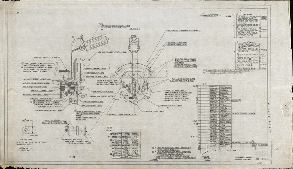
While many of the drawings are considered “experimental”, a large number of drawings in the collection are later revisions that are still used today to manufacture warbird parts and assemblies. “It’s hard to understand the collection without seeing it in real life, and comparing it to the microfilm images that we are so familiar with,” says Ester Aube, the Data and Library Specialist at AirCorps. Details that have been obscured by the darkening of microfilm over time, over-use, or simply deterioration, are revealed on the original drawing with crystal clarity.
Aside from the obvious technical value of the drawings, it’s hard not to appreciate them from an artistic standpoint too. Hearkening back to a time before computers and CAD programs, the draftsmen of North American Aviation created these images with nothing but pencils, drafting tools, and their bare hands – no small feat.
AirCorps unveiled examples from Ken’s collection this weekend at the National Warbird Operators Conference (NWOC) in Mobile, AL, and hopes that others will share their feeling of excitement at viewing these “technical works of art”. Ken has done the vintage and legacy aircraft community a great service through his persistence, and understanding of what these drawings would mean in a historical context. “We cannot thank him enough for the service he performed, and look forward to continuing to work with him as we unpack and sort the drawings,” says Aube.
If you would like more information about the Ken Jungeberg collection, or have additional questions, please contact:
Ester Aube: estera@aircorpsaviation.com
6 Trackbacks / Pingbacks
Graphic Design, Branding and Aviation Art