The Dakota Territory Air Museum's P-47D at AirCorps Aviation in Bemidji, Minnesota. The fuselage is coming close to completion now, with systems installation taking place. Read on for Chuck Craven's latest report on progress with this important project. (image via AirCorps Aviation)
Warbird Digest has just received the June, 2020 report from Chuck Cravens concerning the restoration of the Dakota Territory Air Museum’s P-47D Thunderbolt 42-27609 at AirCorps Aviation in Bemidji, Minnesota. We thought our readers would be very interested to see how the project has progressed since our last article on this important project. So without further ado, here it goes!
Update
The installation of instruments, hydraulic, water injection, and oil tanks was a large part of the restoration work this month. Progress on the wing assembly has also moved forwards as the Thunderbolt gets closer and closer to completion.
Cockpit
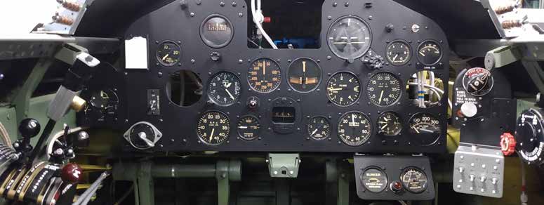
Aaron has been busy continuing systems and instrument installation in the P-47 cockpit.
Completion of the instrument panel only requires a few more instruments to undergo testing and installation, along with application of the decalcomania. (image via AirCorps Aviation)
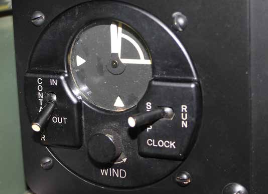
On the left side of the instrument panel is this odd-looking instrument named a BC-608-A Contactor Unit Clock [National Museum of the Air Force, https://www.nationalmuseum.af.mil/ accessed 6/18/2020]. (image via AirCorps Aviation)
Installed in Allied aircraft as part of the Identification, Friend or Foe (IFF) program during World War II, this system would send a signal for 14 seconds of every minute over the pilot’s radio to the ground station. The pilot could not speak while the unit was broadcasting.
Systems installation continues, the upper black control sub-panel has the engine primer and cowl flaps control; the signal light box is attached below. The others will be identified in following detail shots. (image via AirCorps Aviation)
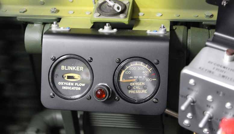
This is the oxygen flow indicator blinker and pressure gauge. (image via AirCorps Aviation)
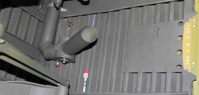
The upwards-pointing tube between the rudder pedals is the fresh air vent. (image via AirCorps Aviation)
Fuselage
Hydraulic system tanks, oil tanks, and the initial fitting of the water injection tank made up much of the fuselage work this month.
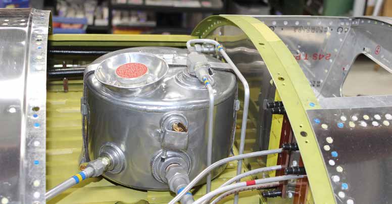
The hydraulic reservoir mounts in a space behind the upper firewall. (image via AirCorps Aviation)
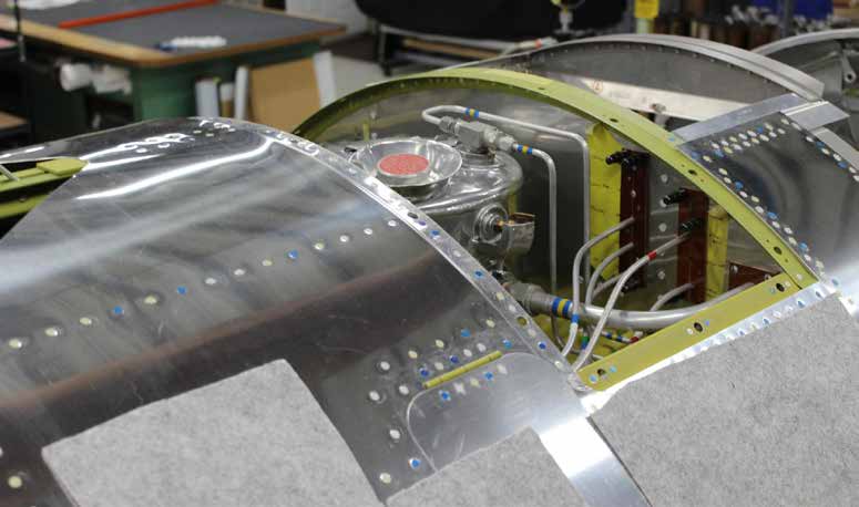
Here is an image from another angle showing the hydraulic reservoir. (image via AirCorps Aviation)
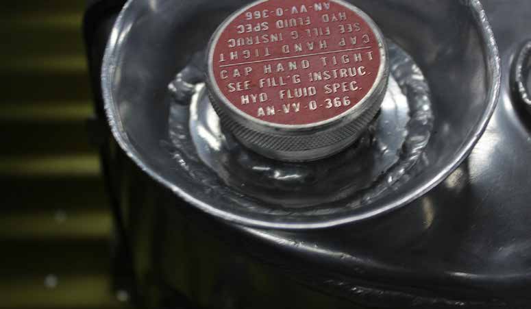
The hydraulic oil reservoir cap label specifies how tightly to attach it, and what fluid to use. (image via AirCorps Aviation)
The silver, cylindrical component seen here is the instrument vacuum filter. Sam managed to locate an NOS (new old stock) example for the project. Its box was unopened and dated May 11, 1942. So until Aaron opened it, this filter hadn’t been touched by human hands in almost exactly 78 years! (image via AirCorps Aviation)
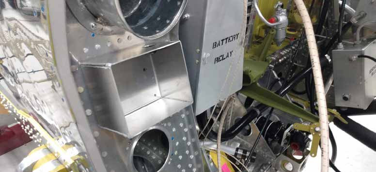
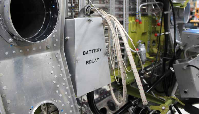
The empty aluminum box seen here will hold a starter relay that is now required by Tech Order 01-65BC-115 issued May 26, 1945. It would not have originally been installed on 42-27609, but a shortage of JH-5B starters (which had a relay built into the starter) necessitated a switch to the JH-4E variety, which required a separate relay. (image via AirCorps Aviation)
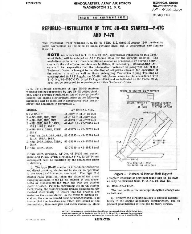
Page one of Technical Order 01-65BC-115 explains the reasons for this modification. (image via AirCorps Aviation)
The battery relay box contains a relay which turns on the main battery power. It also controls the starter, generator, and auxiliary power circuits. (image via AirCorps Aviation)
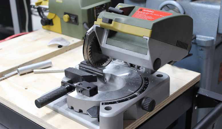
This small metal chop saw has turned out to be very handy for squaring the many tubing ends in the P-47 fuel, oil, vacuum, and hydraulic plumbing systems. (image via AirCorps Aviation)
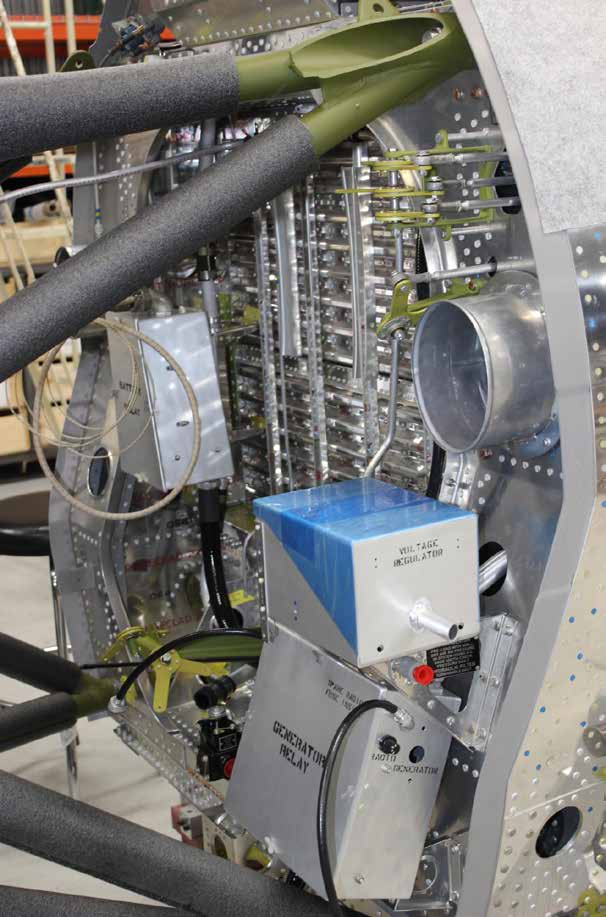
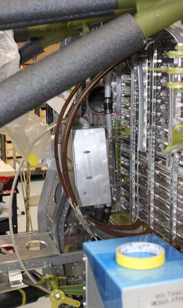
The firewall is looking more complete. (image via AirCorps Aviation)
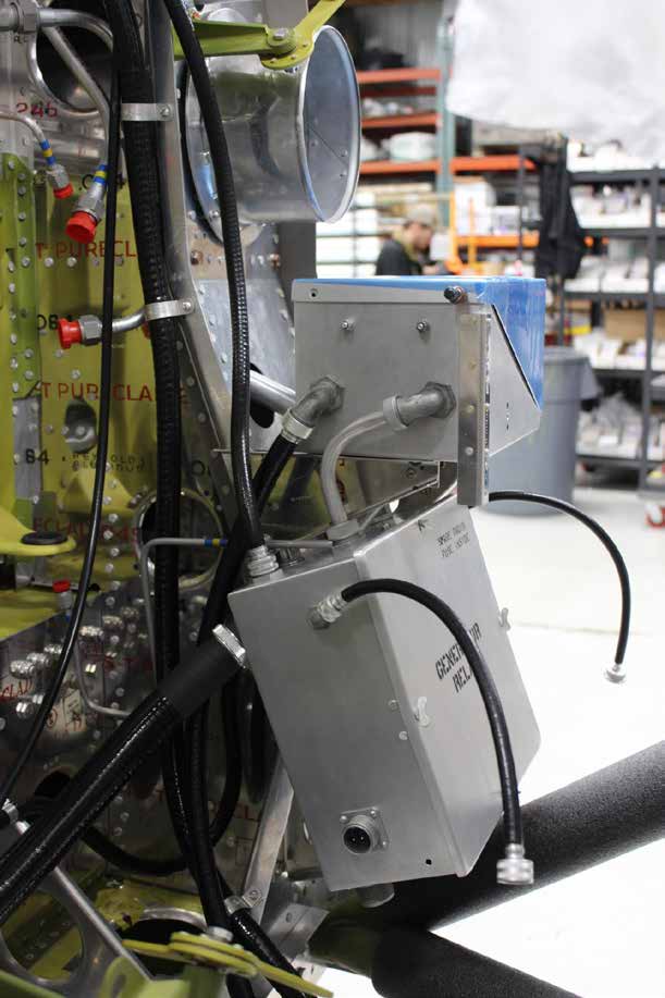
Another firewall view from the other side shows the connection between the voltage regulator and generator relay boxes. (image via AirCorps Aviation)
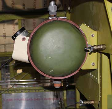
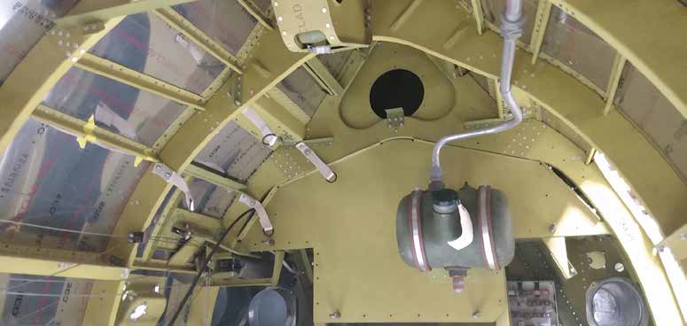
The supercharger oil tank is now permanently mounted on the back of the Christmas tree tank enclosure. (image via AirCorps Aviation)
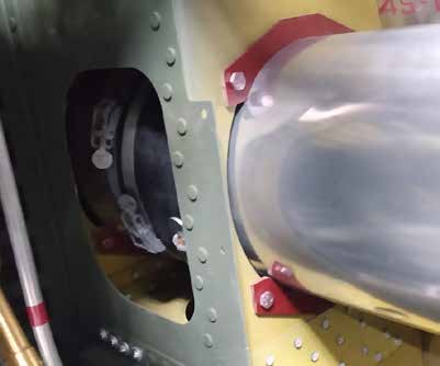
This duct carries pressurized air from the turbosupercharger to the carburetor. It has a sleeve connection, which you can just see in the shadows, located in an extremely tight spot. It was a real challenge to install it in that space without some disassembly of already finished structure. (image via AirCorps Aviation)
This view shows the Christmas tree tank housing from the rear. The turbosupercharger oil tank is visible, including the drain tube on top and fitting for the feed line on the bottom. The webbing straps in the center left of the photo are for stowing the canvas engine cover. (image via AirCorps Aviation)
Oil Tank
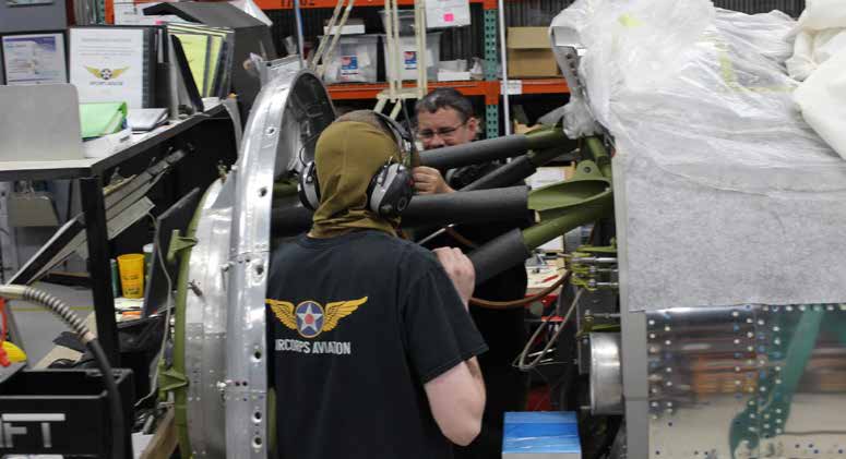
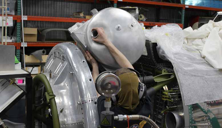
Aaron needed to put the engine oil tank in place to fabricate some oil lines; Lance and Aaron are seen here discussing how to accomplish that. (image via AirCorps Aviation)
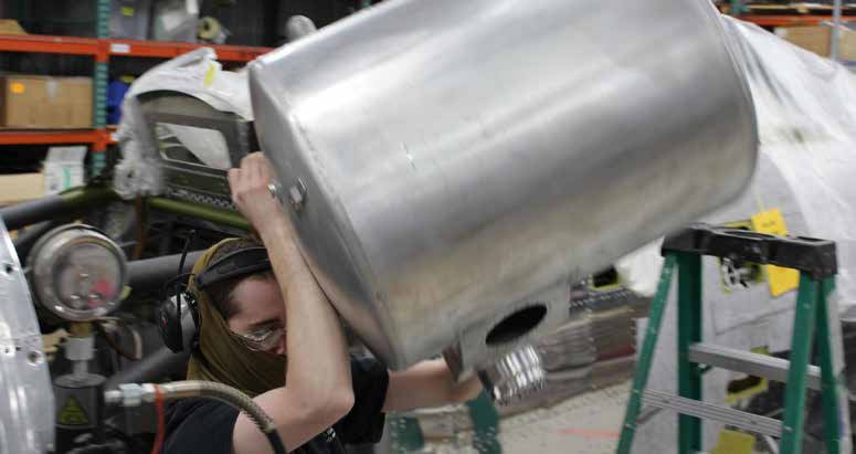
Aaron carries the tank over. (image via AirCorps Aviation)
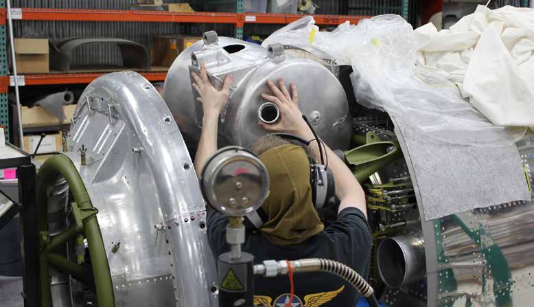
Aaron and Lance are almost ready to put the tank in place. (image via AirCorps Aviation)
They work the tank into place. (image via AirCorps Aviation)
It took a lot of wiggling and adjusting to get the tank into the crowded accessory area.(image via AirCorps Aviation)
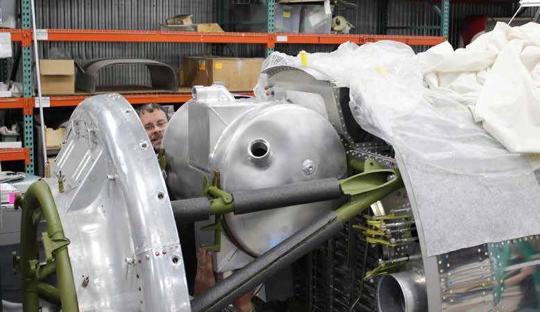
At last! The oil tank is in position. (image via AirCorps Aviation)
Water Tank
The P-47D-23RE had a 15 gallon tank to hold fluid for the water injection system. Water/Alcohol injection cools the flame temperature and controls flame propagation, thus preventing detonation, which can break piston rods and pistons. These systems allowed for higher manifold pressure, and added 300 Horsepower at the push of a button on the throttle quadrant [Graham White, Allied Aircraft Piston Engine of WWII, Warrendale, PA, Society of Automotive Engineers, 1995, p244]. The tank allowed about 5 minutes of power-boost. Later versions of the P-47 (P-47D-25RE and subsequent) doubled the capacity of the water tank.
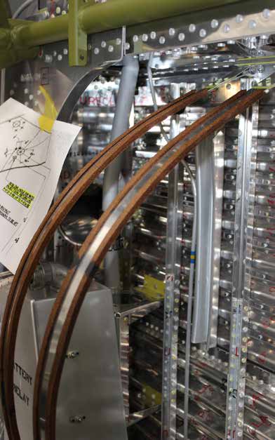
The brown colored straps in this photo will hold the water injection tank to the firewall. (image via AirCorps Aviation)
This closer image shows the metal straps cushioned with cork insulation strips. (image via AirCorps Aviation)
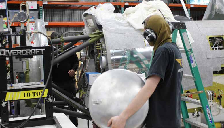
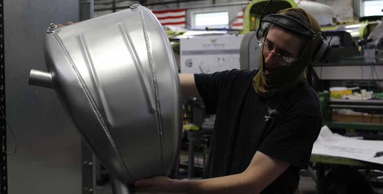
Aaron holds up the water tank. (image via AirCorps Aviation)
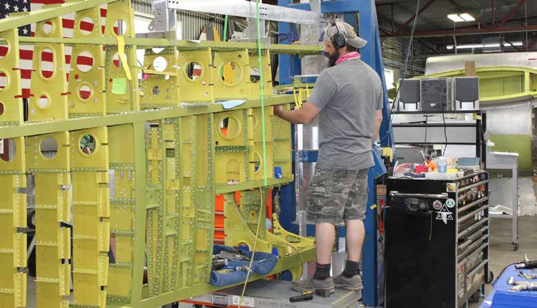
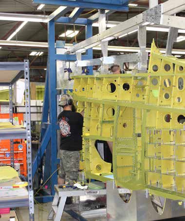
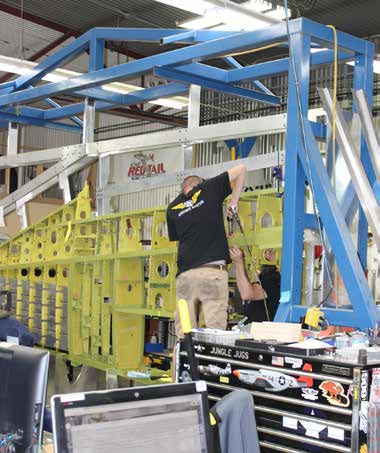
Wings
The wings are complex and take a long time to assemble, but progress continues.
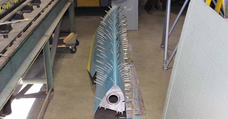
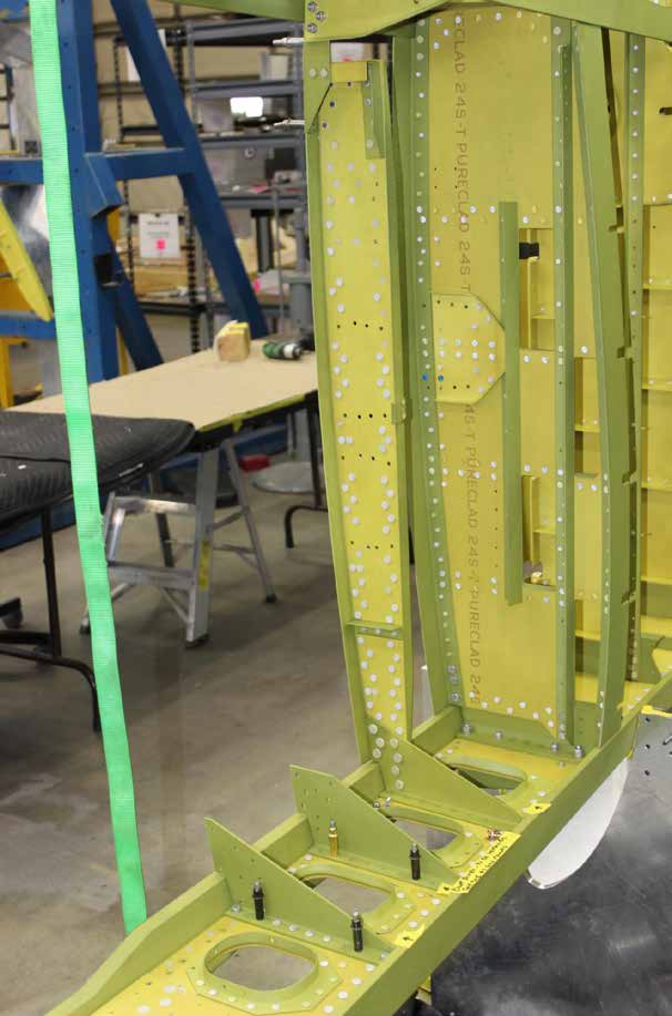
Some preliminary wing skin fitting is visible on this leading edge section. (image via AirCorps Aviation)
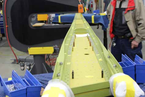
Ribs are now permanently riveted to spar #2. (image via AirCorps Aviation)
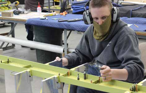
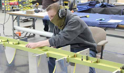
The fixture holds spar #1 as Cory works. (image via AirCorps Aviation)
Cory continues assembly of spar #1. (image via AirCorps Aviation)
Several tables are needed to stabilize the long spar as the rivets are being squeezed. (image via AirCorps Aviation)
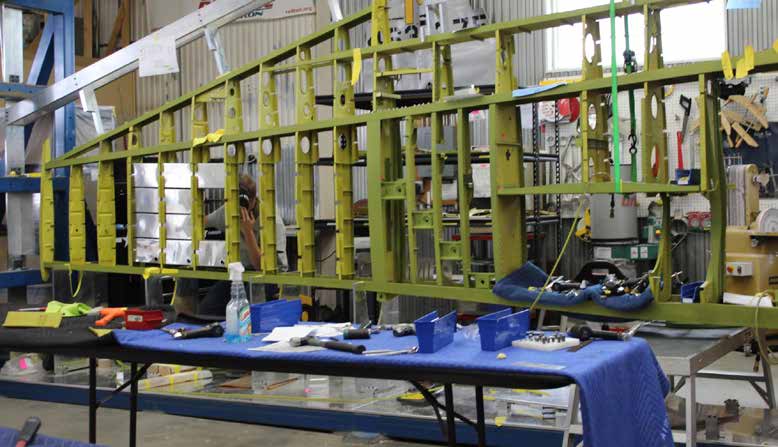
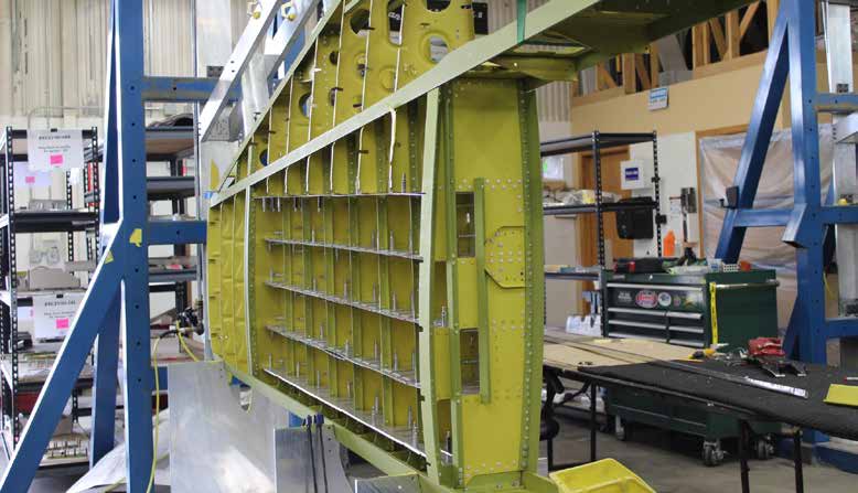
Progress in final assembly and riveting on the left wing is shown clearly in this shot. (image via AirCorps Aviation)
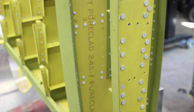
These ribs are in the gun bay area, viewed from the bottom of the wing. (image via AirCorps Aviation)
The same area viewed from the top. (image via AirCorps Aviation)
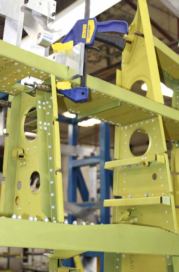
This part of the wing is where the flap fits (the area with the clamp). (image via AirCorps Aviation)
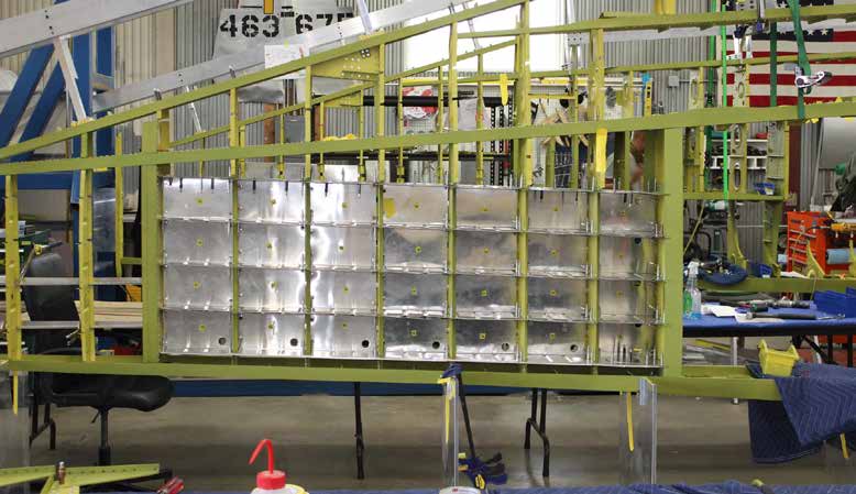
The right wing is shown here with the gun bay ribs in place. (image via AirCorps Aviation)
The ammunition feed chutes (bare aluminum) have been clecoed in place. (image via AirCorps Aviation)
Randy is preparing to buck a rivet. (image via AirCorps Aviation)
Randy on this side of the wing works with Cory on the other side as they rivet. (image via AirCorps Aviation)
Cory drives a rivet as Randy bucks. (image via AirCorps Aviation)
Armament and Drop Tanks
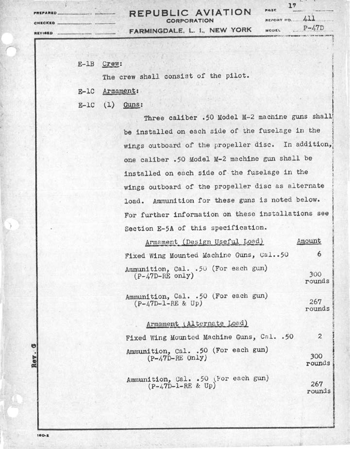
The P-47 was a versatile fighter/fighterbomber. Bombs, rockets, and of course .50 caliber machine guns, were all part of the possible armament loads. Many different drop tanks were used in the quest to extend the range. The most common tanks and ordnance are shown below. Normally, the P-47 could carry six or eight .50 cal. machine guns, and either 10 rockets or 2,500lbs of bombs, or any combination that totalled 2,500lbs. British 5 inch rockets were also used.
(image via AirCorps Aviation)
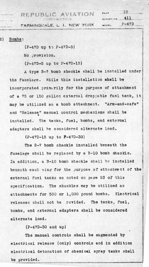
Here is an interesting Republic Aviation document that originally specified 3 .50 caliber Brownings in each wing with a four gun wing as an alternate load. Bomb shackles are also specified on the second page. The vast majority of combat P-47s carried four guns in each wing. (image via AirCorps Aviation)
The eight .50 caliber Browning M-2s are familiar, so we will examine the more common drop tank and bomb and rocket loads.
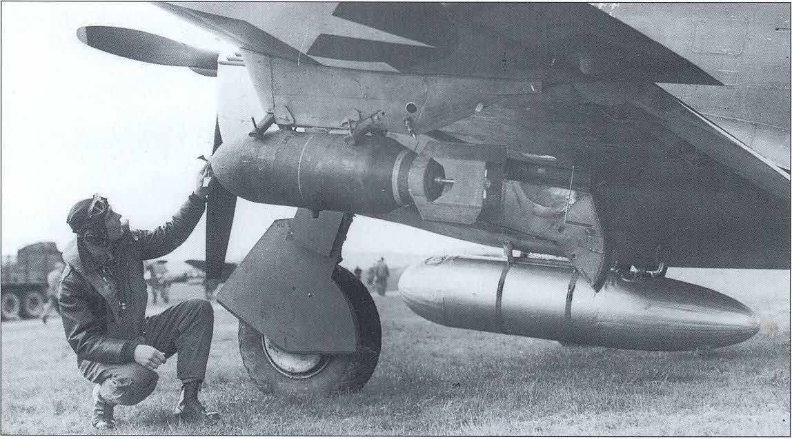
A pilot inspecting a 500lb bomb under the port wing of his Thunderbolt. A 200 gallon ‘paper’ centerline drop tank is visible under the fighter’s fuselage, USAAF photo. (image via AirCorps Aviation)
A variety of different drop tanks were fitted to the Thunderbolt during the type’s career. The earliest tanks were the conformal 200 gallon ferry tanks, and the lozenge-shaped, flat 200 gallon belly tank. The P-47 also used British-designed, 108 gallon and 200 gallon tanks made of plastic-impregnated paper. These “paper” tanks were relatively inexpensive, but couldn’t store fuel for long periods of time. With the increased fuel capacity gained from drop tanks, the P-47 was able to perform missions far deeper into enemy territory.
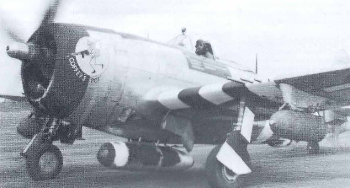
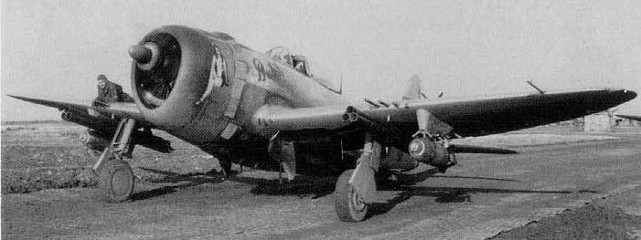
This photo shows the British-designed, 108 gallon, paper drop tank on the centerline and 1000lb bombs on the wings. The B-10 shackles for the bombs are mounted in the wing pylons, USAAF photo. (image via AirCorps Aviation)
75 gallon drop tanks. USAAF photo. (image via AirCorps Aviation)
Later, P-47 squadrons adopted teardrop-shaped 75 US gallon and 150 US gallon metal wing drop tanks. The 165 gallon teardrop tank, first intended for the P-38, was another drop tank P-47’s used.
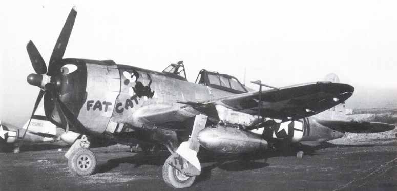
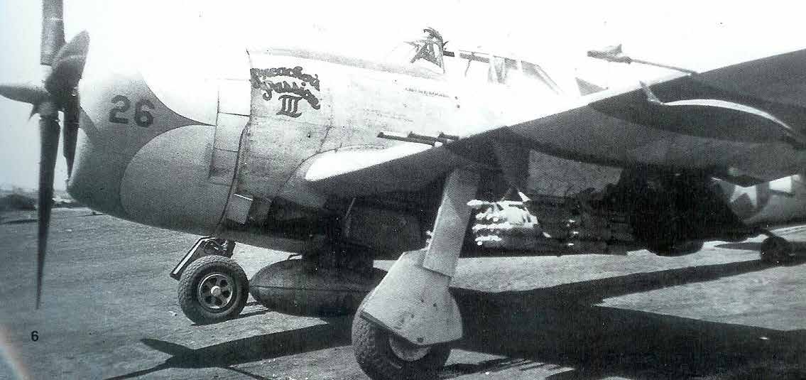
Preacher’s Passion III, 39th Fighter Squadron, with 75 gallon centerline drop tank and cluster bombs. USAAF photo. (image via AirCorps Aviation)
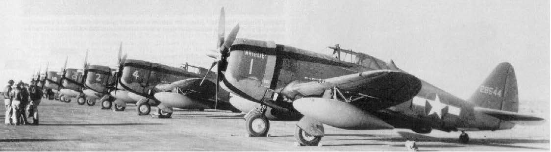
165 gallon P-38 drop tanks are seen on these Thunderbolts. USAAF photo. (image via AirCorps Aviation)
4.5 inch Rocket tubes and 500 pound bombs. USAAF photo. (image via AirCorps Aviation)
And that’s all for this month. We wish to thank AirCorps Aviation, Chuck Cravens for making this report possible! We look forwards to bringing more restoration reports on progress with this rare machine in the coming months, although it will likely be some time before we can do so given how the present pandemic has suspended almost all non-essential activities around the globe at the moment. Be safe, and be well


Be the first to comment
Graphic Design, Branding and Aviation Art