

Warbird Digest has received the September/October, 2021 report from Chuck Cravens concerning the restoration of the Dakota Territory Air Museum’s P-47D Thunderbolt 42-27609 at AirCorps Aviation in Bemidji, Minnesota. We thought our readers would be very interested to see how the project has progressed since our last article on this important project. So without further ado, here it goes!
Update
This month, work on the control surfaces continues; the turbosupercharger system ducting is also progressing nicely. We also reached two exciting milestones in October, fitting the landing gear to the wings and an R-2800 to the engine mount for firewall forward mock up work.
In the history section, we look into the long-range challenges a pilot had to endure on missions lasting as much as 8 hours in a tropical climate.
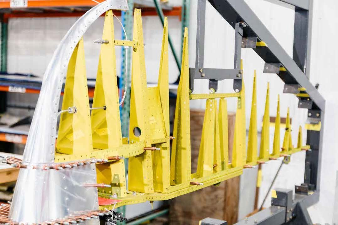
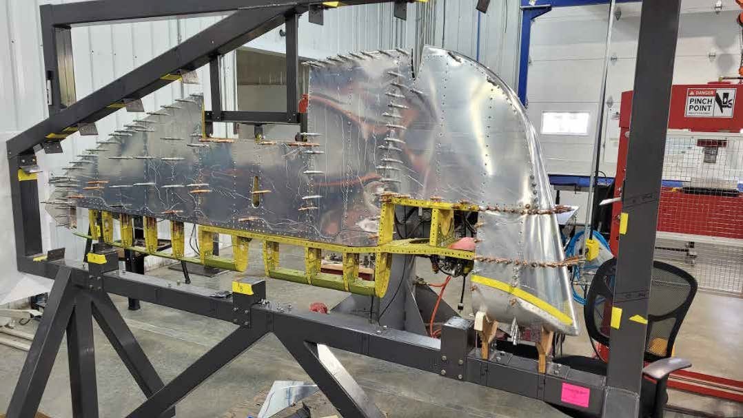
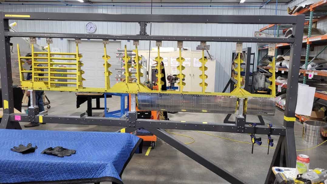
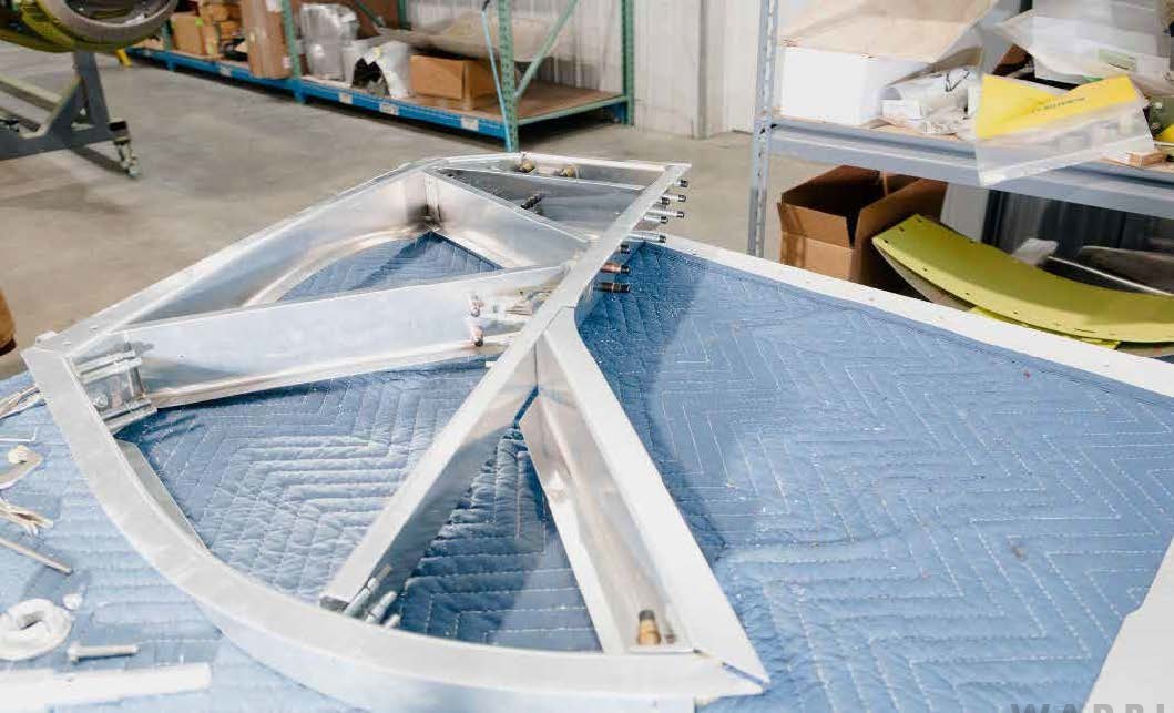
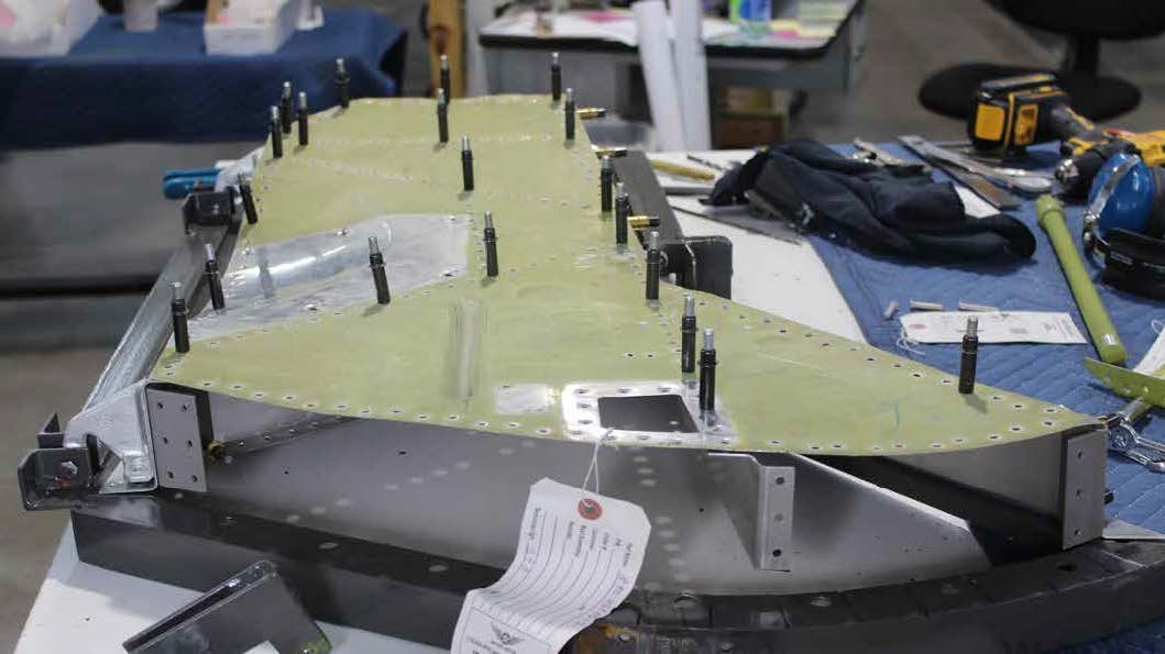
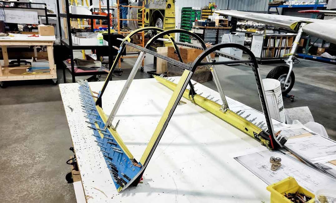
Control Surfaces
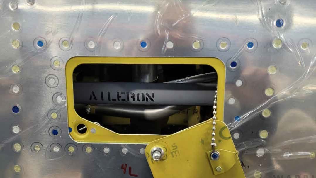
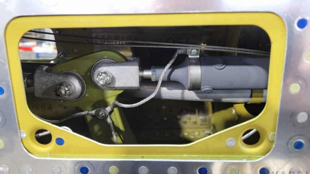
Work on the rudder, flaps, and aileron linkage was a big part of the restoration work this month.
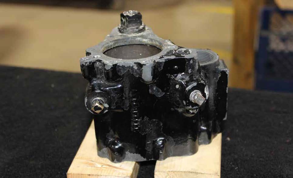
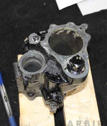
Main Landing Gear
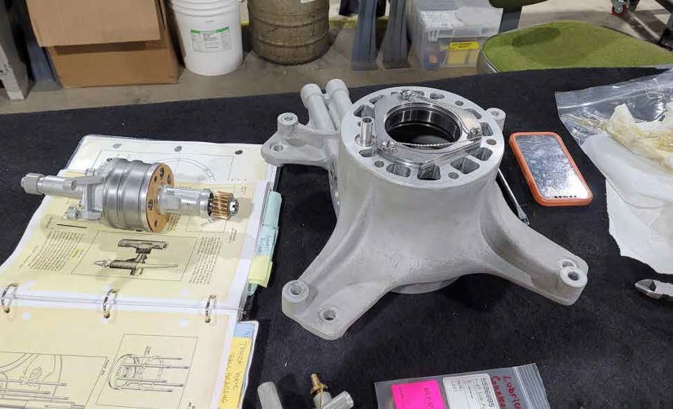
The main landing gear assemblies require a great deal of precision fitting to be sure they will function flawlessly. They were fitted, adjusted and installed in October.
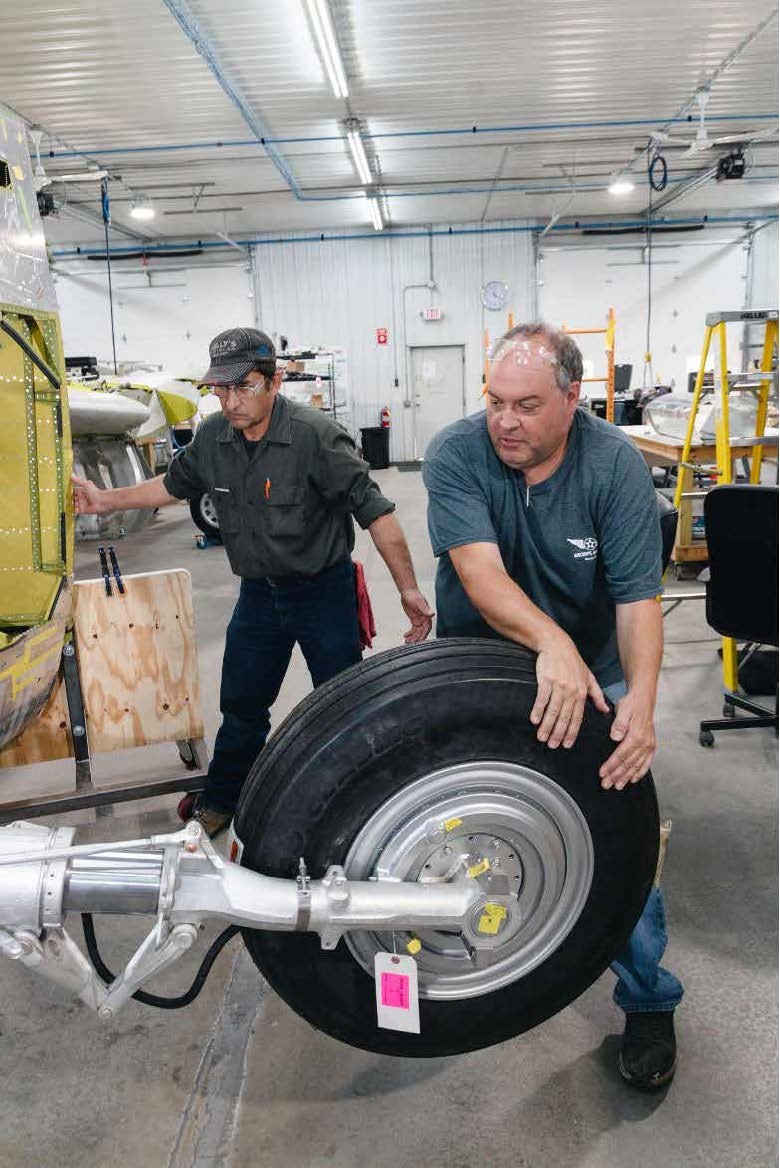
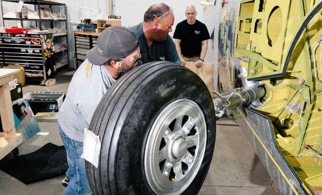
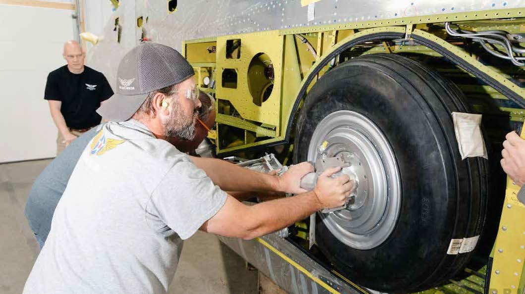
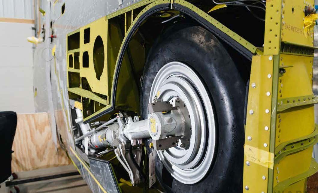
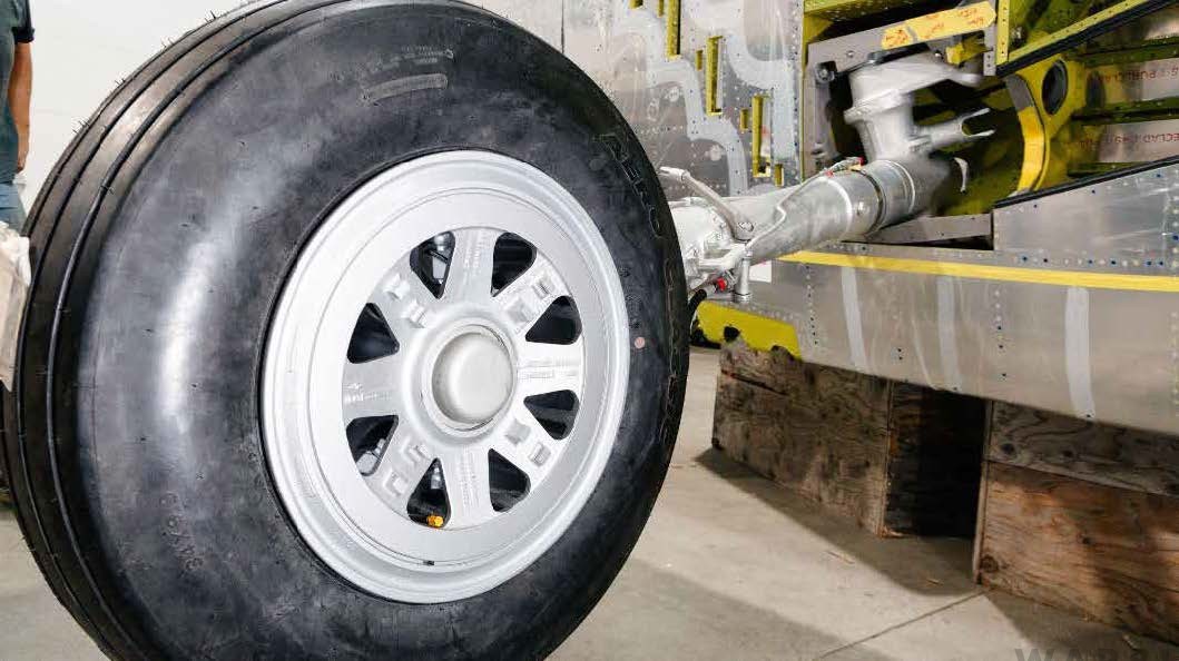
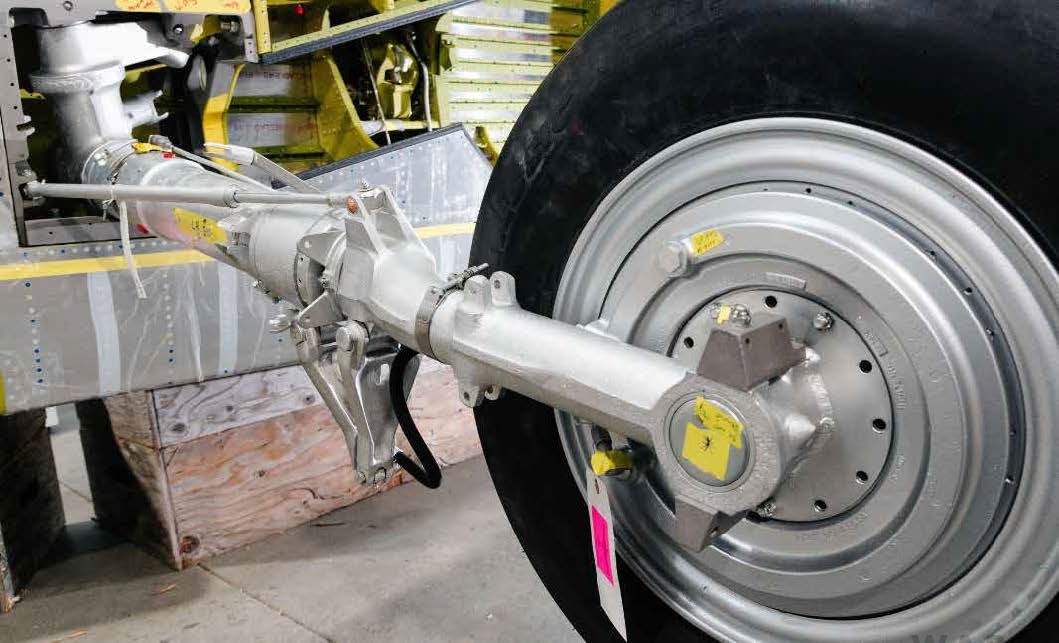
(image via AirCorps Aviation)
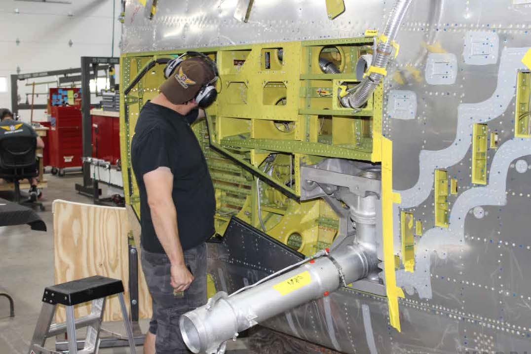
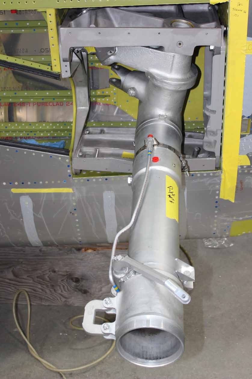
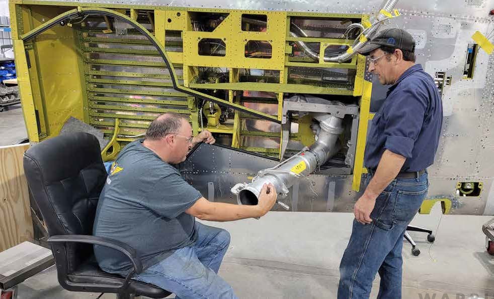
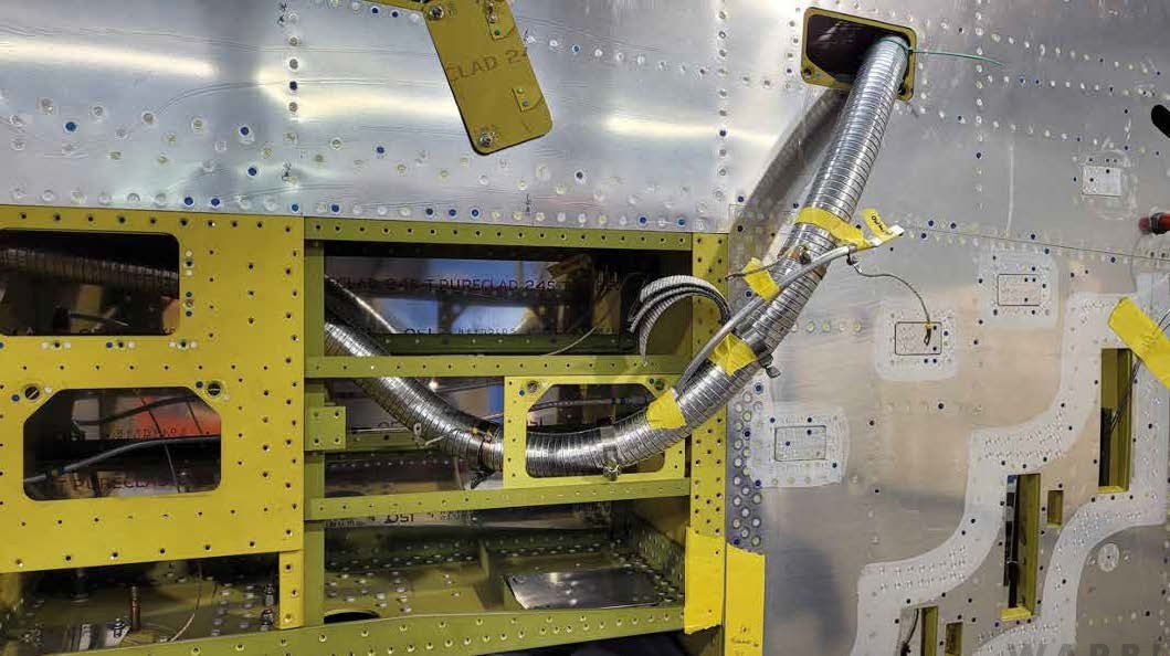
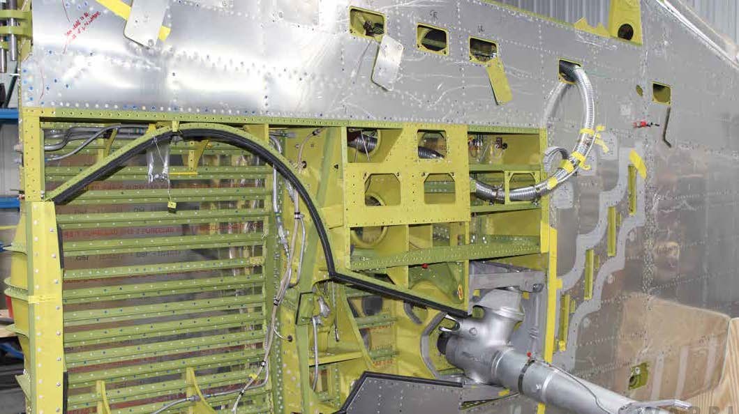
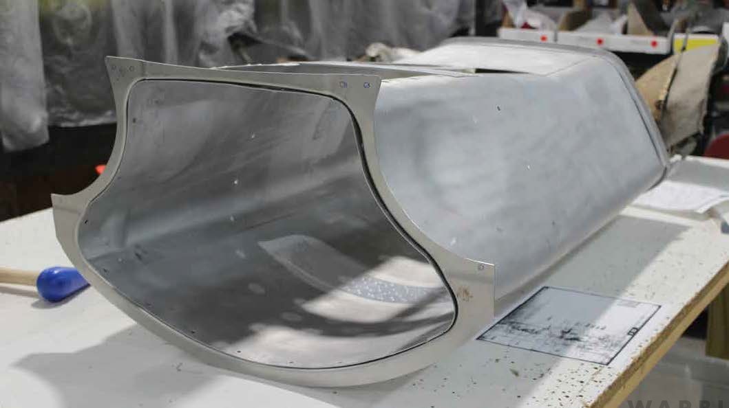
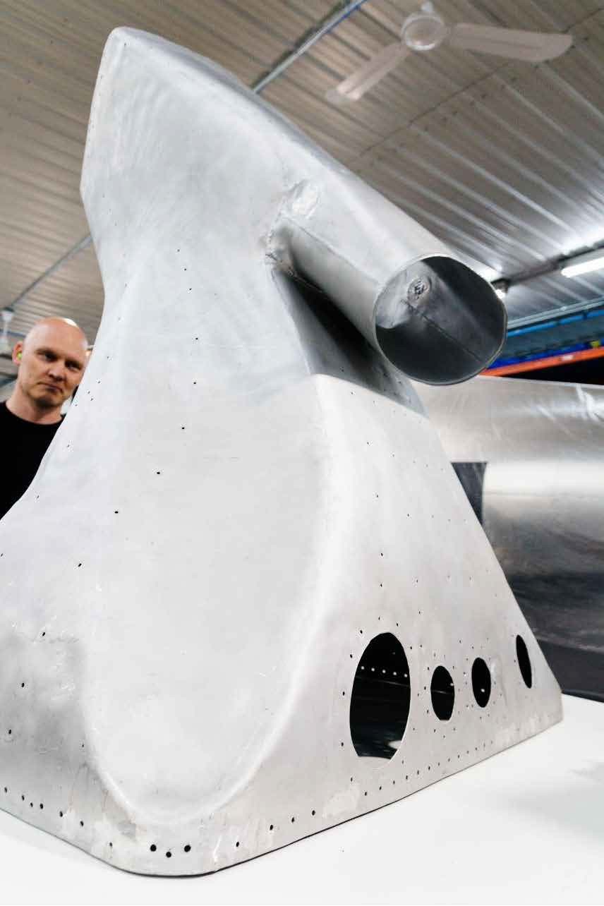
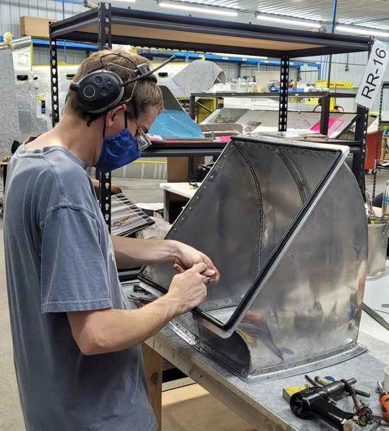
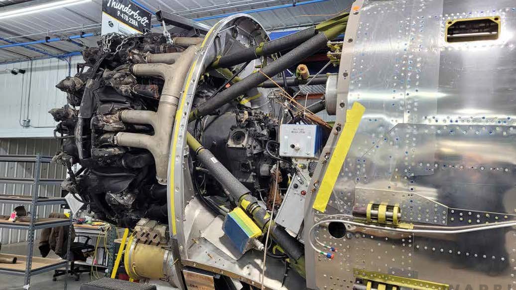
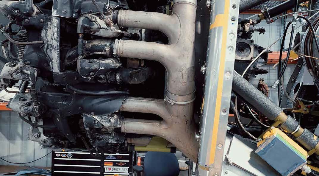
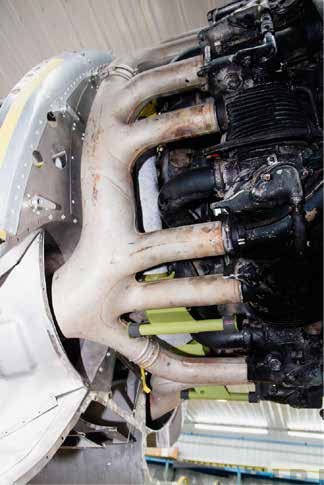
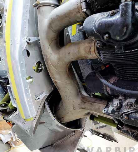
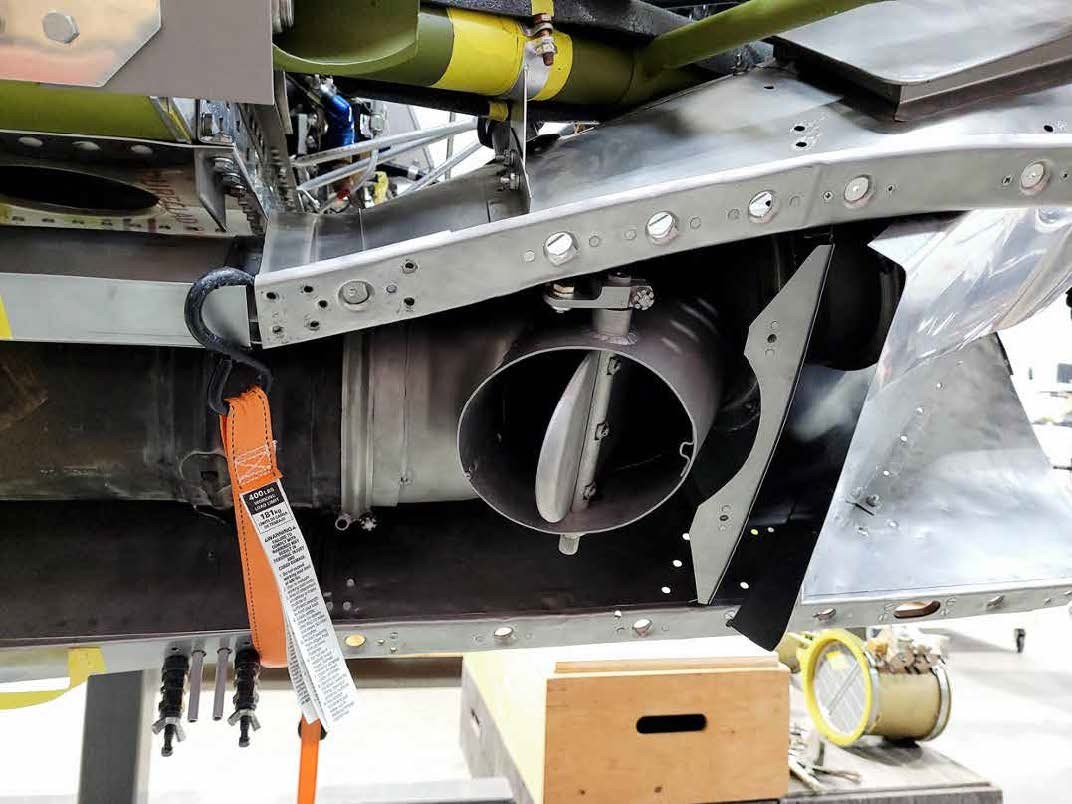
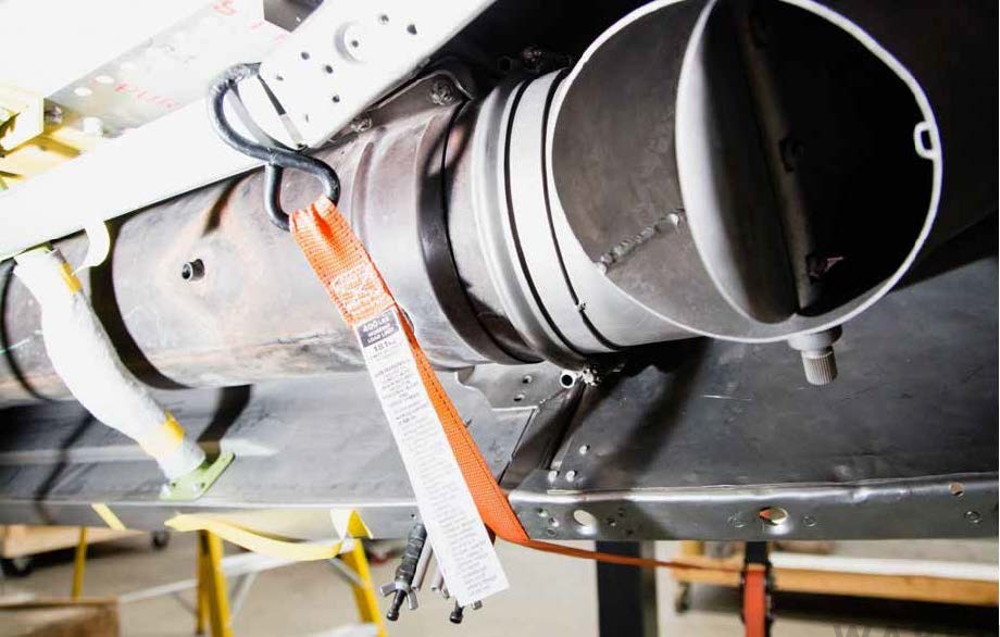
Induction and Turbosupercharger System Parts
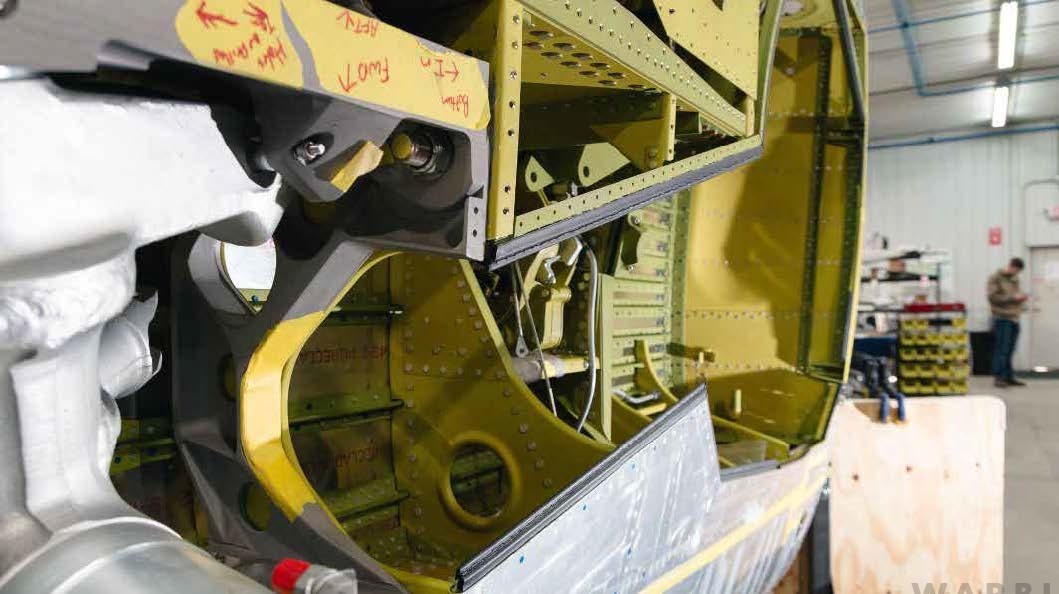
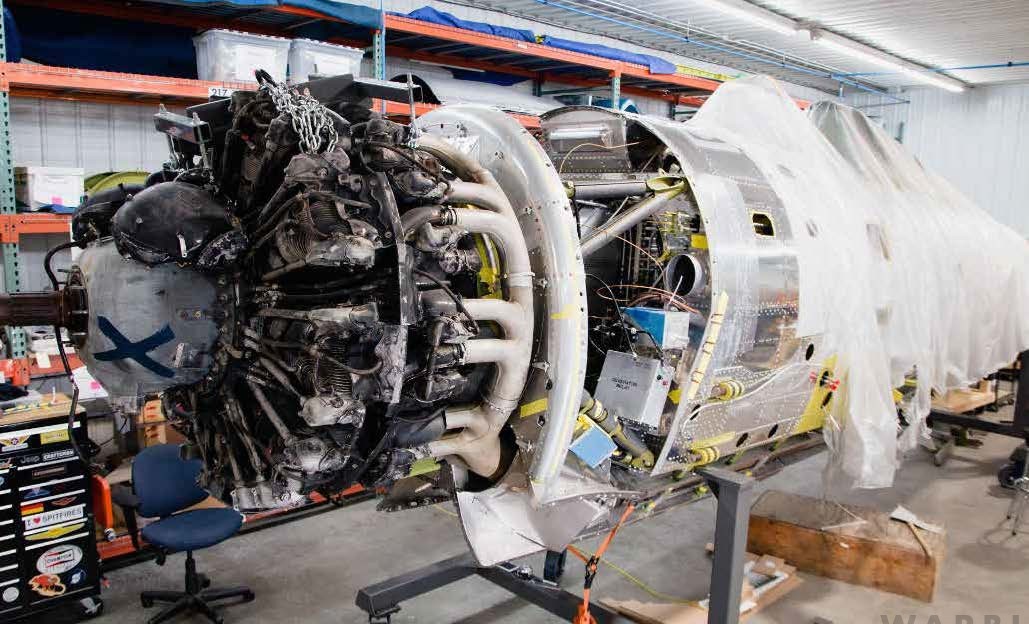
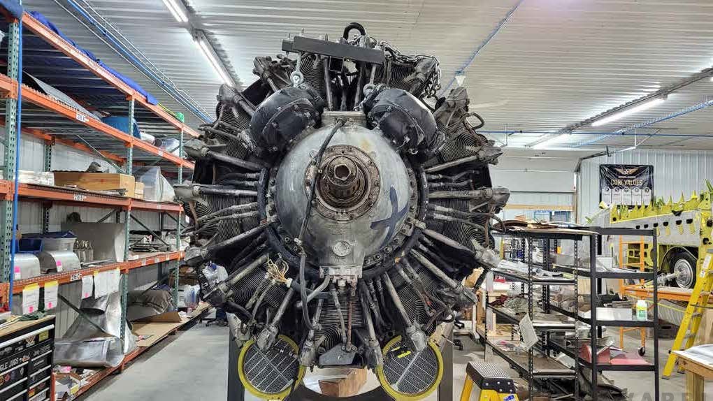
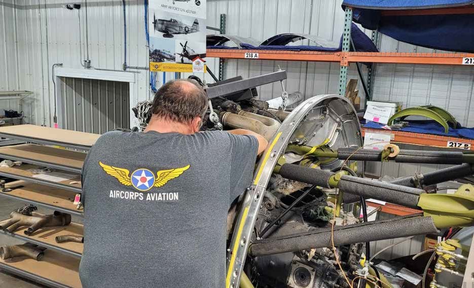
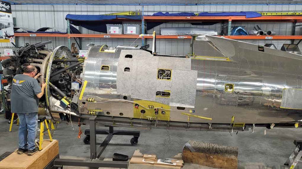
Firewall Forward
One of this month’s milestones was the trial installation of an engine for mock up purposes. This allowed all of the connecting assemblies to be fitted in readiness for delivery of the airworthy overhauled R-2800.
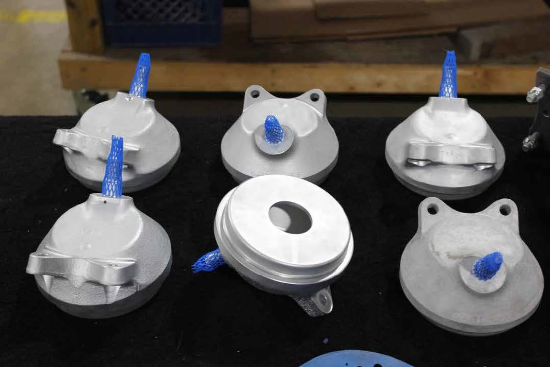
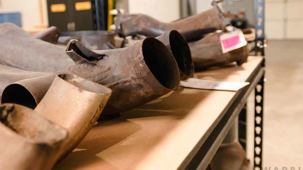
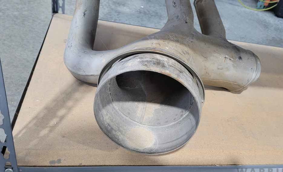
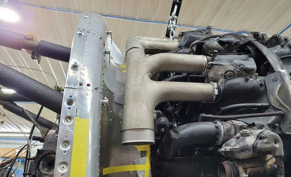
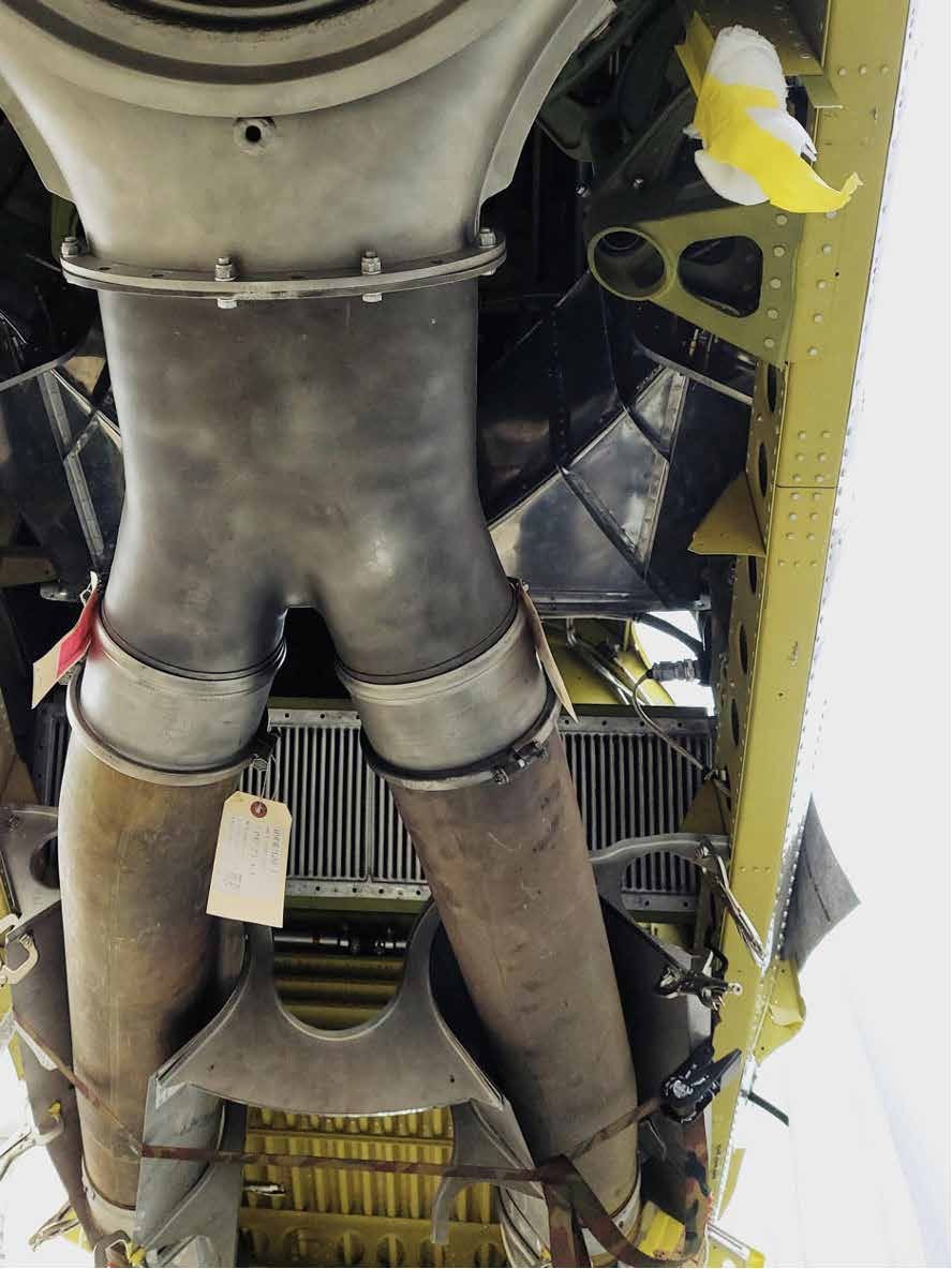
of the exhaust manifold. (image via AirCorps Aviation)
The Long Range Missions
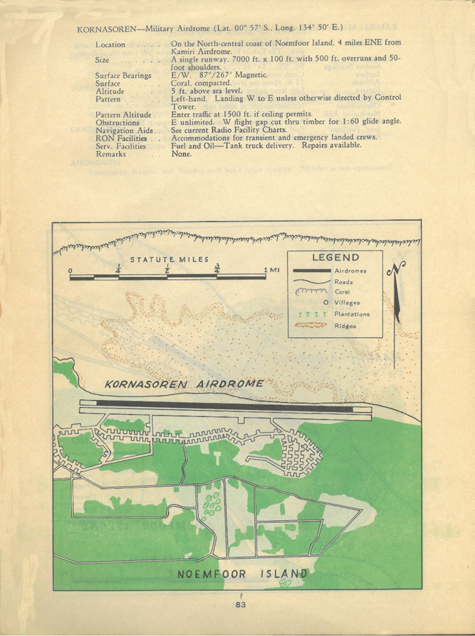
Flying from Nadzab on August 7, 1944, Major Richard Cella led a flight of twenty-six of the newly-received P-47D-23s on a 900 mile mission to Noemfoor. This mission involved providing defensive cover for the SeeBees constructing new airfields on Middleburg Island below them. Similar missions continued for 6 weeks, but the 39th was able to move up to Noemfoor earlier than that.
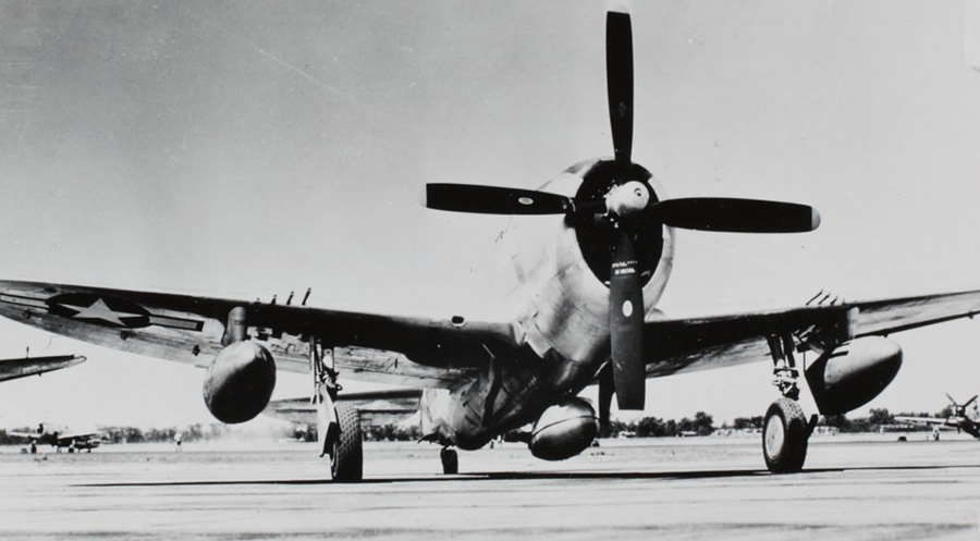
The 39th conducted its first operations from Noemfoor on August 9th. Noemfoor offered some significant advantages with its 7,000 foot, compacted coral runway. Continued testing to verify maximum permissible takeoff loads could be conducted on the long, smooth, and relatively unobstructed runway; the squadron settled on two 175 gallon tanks under the wings, with an additional 75 gallon belly tank. The combined total of these three tanks, 425 gallons of fuel, added 2,550 lbs. to the takeoff weight. With this additional weight, the P-47’s minimum take off speed proved to be between 125 and 130 mph, 15 to 20 mph higher than what the Thunderbolt needed without the drop tanks fitted.
During this time period, the legendary aviator, Charles A. Lindbergh visited various 5th AF and Navy fighter groups as a consultant. His role was to help improve range and load carrying performance for the fighters in use in the Southwest Pacific Theater of Operations.
Lindbergh visited the 35th Fighter Group on August 14, 1944 and presented his increased range procedures.1
He demonstrated how raising manifold pressure and lowering engine revolutions, could greatly improve P-47 fuel economy, and hence the aircraft’s range.
On August 20th, another long range mission involved a fighter sweep led by Captain Gordon Prentice. The duration of that sortie extended to over 5 hours and 20 minutes, making it the longest mission the 39th Fighter Squadron had flown thus far, and perhaps the longest of any 5th AF mission to date.2
1 Charles A. Lindbergh, The Wartime Journals of Charles A. Lindbergh, Harcouirt, Brace, Jovanovoch, Incv., New York, New York, 1970,p 905-906
2 John Stanaway, Cobra in the Clouds,Historical Aviation Album 1982.
With the maximum range techniques Colonel Lindbergh encouraged, together with the knowledge learned from the experiments which the squadron’s pilots conducted, the P-47 could now perform missions of nearly triple the range experienced before these innovations.
“No longer would the skeptics berate the P-47’s range. Later in the year, the squadron registered missions up to eight hours.”3
These techniques certainly increased the Thunderbolt’s combat utility in the Southwest Pacific, but what is seldom discussed is the price pilots paid for these extended missions. To take advantage of the technique of high manifold pressure and low rpms, the long range flights had to be flown at low altitudes. High enough manifold pressure couldn’t be maintained at the low rpms if the P-47s flew much higher than 3,000 feet.
A P-47’s pilot sits just above two tubes which supply hot exhaust gases to drive the turbosupercharger and just behind the big radial R-2800, both of which generate a lot of heat. Even in a tropical environment like New Guinea, where triple digit temperatures on the ground were common, pilots would normally mitigate the heat to some degree by climbing to an altitude which was cooler. Unfortunately for them however, the new long range techniques didn’t permit that option, so pilots now sweated in their cockpit for as long as 8 ½ hours at a time. They would often return home dangerously dehydrated and exhausted from missions like these.
3 John Stanaway, Cobra in the Clouds, Historical Aviation Album 1982, Temple City, CA, p.29
And that’s all for this month. We wish to thank AirCorps Aviation, Chuck Cravens for making this report possible! We look forwards to bringing more restoration reports on progress with this rare machine in the coming months. Be safe, and be well
Be the first to comment
Graphic Design, Branding and Aviation Art