


WarbirdsNews has received the latest XP-82 Twin Mustang restoration update from Tom Reilly at his workshop in Douglas, Georgia. Here’s what they’ve been up to this month!
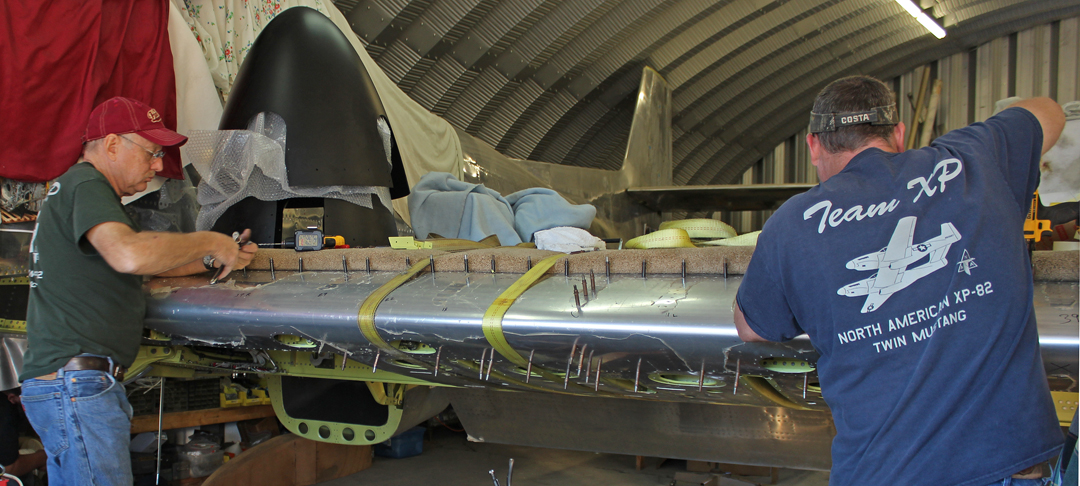
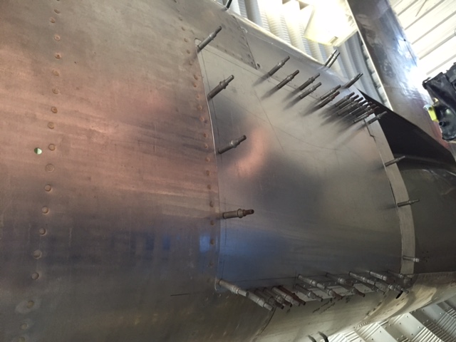
Center Section Leading Edge Assembly
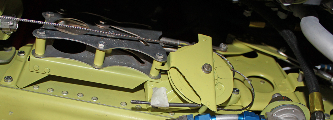
This leading edge sub-assembly has been completed for some time now, and two team members spent a week fitting it to the leading edge spar. This was a complex job as it had to fit around and in between all of the forward gear door up-lock mechanisms mounted on the forward spar. Also, the six gun ports had to be properly positioned in the leading edge skin to align with the .50 cal. gun barrel blast (cooling) tubes. The leading edge assembly must remain off to perform the preliminary adjustments of the gear door up-locks during the gear retraction tests.
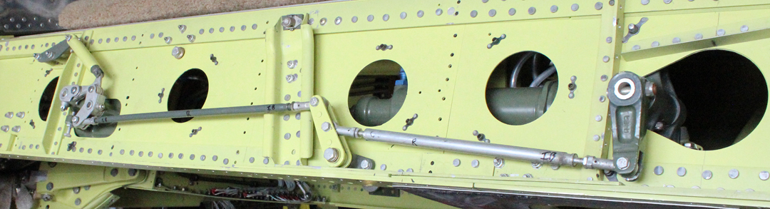
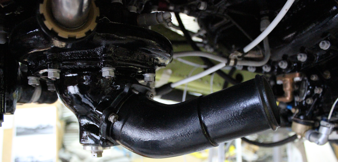
Belly Scoops/Radiators/Coolant Header Tanks
The final two Dzus/nut plate panels that close out at and aft of the bottom of each radiator have now been completed. All four feed and return 2” coolant lines are now completed, along with the 1.25” intercooler lines.
Both pressure relief valves, one mounted on each coolant header tank, are now overhauled and installed.
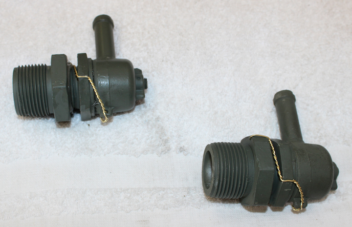

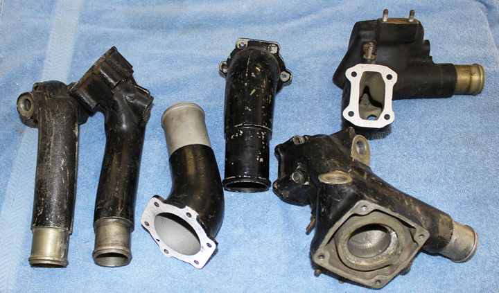
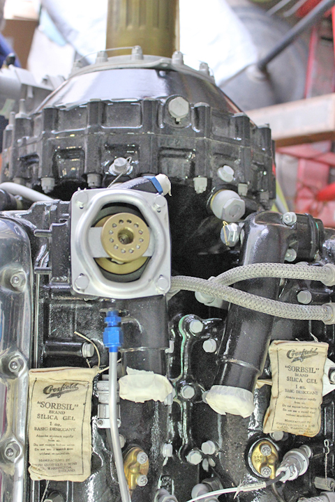
Special XP-82/P-51 Coolant Water Necks
These coolant water necks are peculiar to only the Merlin-powered XP-82 and P-51H engines. They were not included with the overhauled engines as they are considered part of the cooling system. With much searching Nixon Vintage V-12s (the facility in Tehachapi CA, that overhauled the two engines) came up with two pairs of them. They are now permanently installed on both engines.
Firewall Forward Jobs
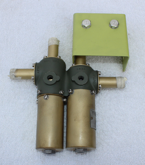
The majority of December was spent completing all of the miscellaneous must-be-completed firewall-forward jobs. All of the feed and return vacuum lines from the vacuum pumps to each firewall and air/oil separators have now been completed.
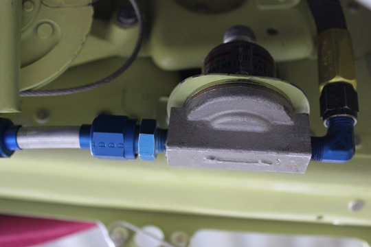
On the left-hand firewall, there is a pressure-controlling valve that manages the vacuum pump discharge pressure airflow through pilot-selected lines out to drop tank mounted on each wing. This vacuum pump discharge pressure is used to pressurize each drop tank in order to push and transfer the fuel without the help of a fuel pump back through return lines to the 95-gallon inboard fuel tank, a unique design. The team managed to salvage enough airworthy parts from three water-damaged valves in their collection to restore one good valve.
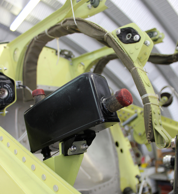
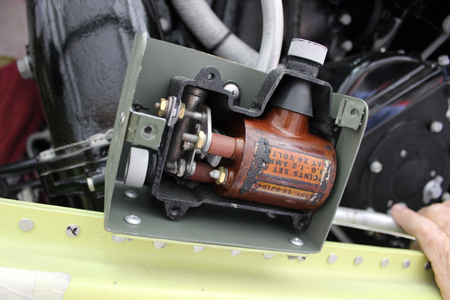
Two vacuum air/oil separators, two ignition starting boosters in their mounting boxes, two pre-oil solenoids and check valves, two tach generators and the two electric/mechanical carburetor air control mechanisms have now been permanently installed on the airframe.
Temperature Probes (Oil and Coolant), Chip Detectors & Drain Ports
On a number of the coolant and oil lines, temperature resistance probes are threaded into special welded fittings in each line. These electrical-resistance probes sense the coolant and oil temperatures and their ohms resistance is transmitted through DC wiring to the respective instrument in each cockpit to indicate the temperatures. Also on the lower point of a number of oil and glycol tubes, there are welded-in drain ports and, on each oil return line, there are chip detectors threaded into welded tube fittings.
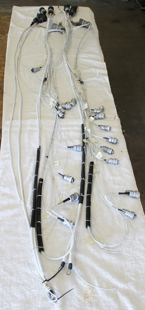
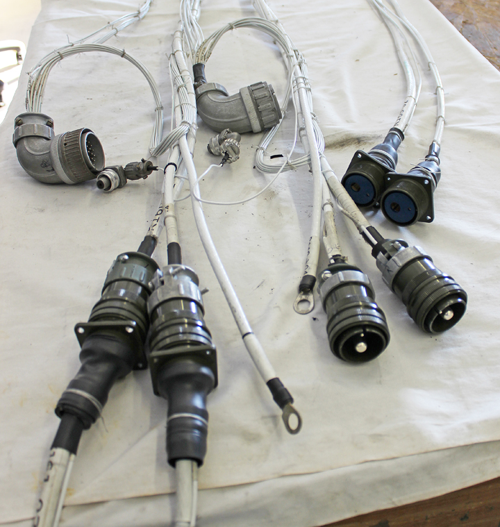
Both entire Firewall forward electrical harnesses have been final installed and attached using Adel clamps and wired in through Cannon plugs to numerous respective locations (generators, starters, tach generators, temperature probes, primers, chip lights, carb air temperature motor controls for induction air temperature, pre-oil, feather pumps, etc.).
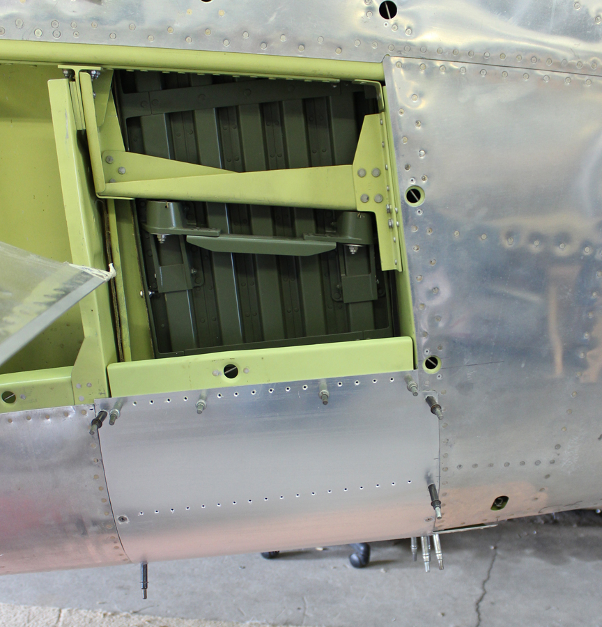
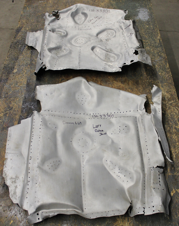
Inboard Gear Doors
Reilly’s team has just started manufacturing two inboard gear doors. These doors are exceptionally complex riveted and spot-welded assemblies. The Alaskan wreck site yielded two extremely munched doors without one reusable part. However, the damaged door parts are revealing a huge amount of information on how to manufacture new parts and how they go together. Completing these two complicated doors will take some time.
And that’s all for December, 2015!
Many thanks again to Tom Reilly for the update! You can learn more about the project on their blog HERE. Please be sure to check back with WarbirdsNews in February for the next installment in the story following the XP-82′s road to recovery!
Work looks outstanding. I saw an XP-82 at the CAF in Harlingen, TX back in the early 80’s. Could this be the same aircraft?
NO Don, the “CAF’s P-8″2 is the one exhibited a the National Museum of the United States Air Force in Dayton. This one was in the Walter Soplata’s collection.
I visited Walt’s place a couple of times while he was in good health. I remember th 82 very well. Walt said that he regularly put oil in & pulled the props thru on it. I also remember a 4360 wasp radial engine that was sitting in front of it on the other side of the path. I believe that it belonged to the f2g corsair of dick becker
How many P-82’s were built? I recall one sitting outside in the Texas sun, in 1966 at Lackland, AFB, San Antonio, Texas, when I was in basic training. It was sitting next to a P38, baking in the sun. I thought it was a shame it was sitting there at the time.
Steve. Old Dominion Squadron CAF, Franklin, VA
Lackland still has that aircraft, outdoors, painted in black “night fighter” scheme, with the canopy painted blue.