

WarbirdsNews has received the latest XP-82 Twin Mustang restoration update from Tom Reilly at his workshop in Douglas, Georgia, and we thought you would all be pleased to see the latest progress!
Firewall Forwards:
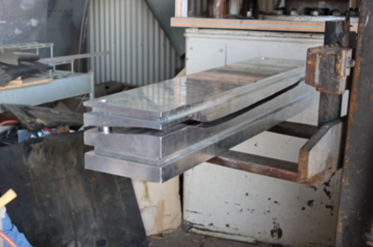
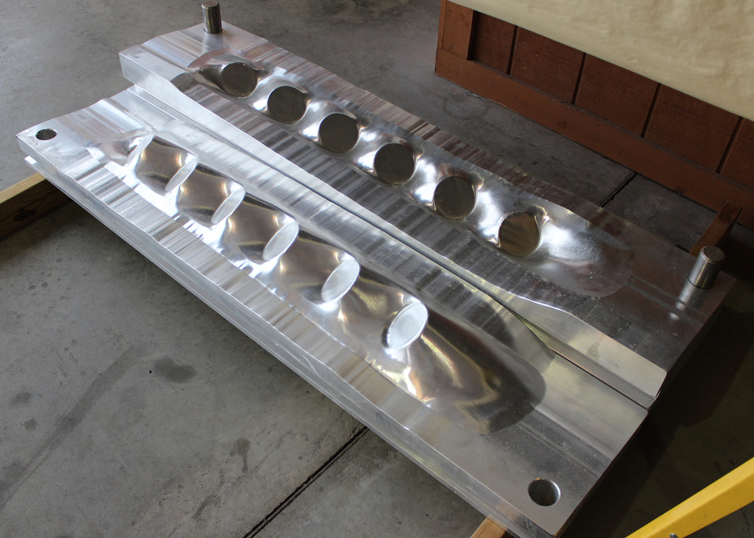
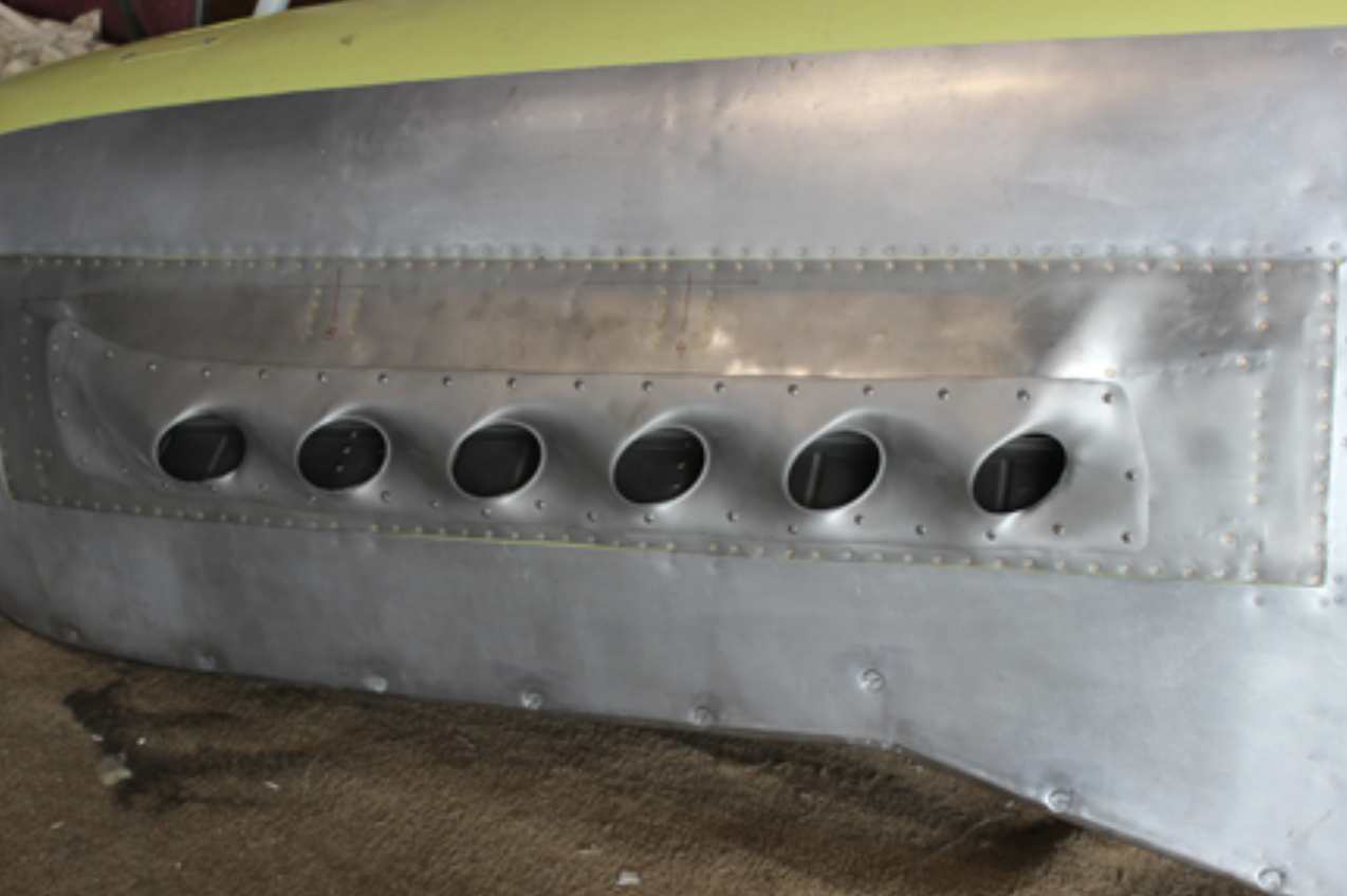
Two team members were able to successfully press both exhaust fairings, trim-to-fit and punch out the twelve exhaust port openings. With a small amount of final hand forming, they had them fitted, drilled and attached to both right-hand engine cowlings. They were able to use the project’s 200-ton rubber press machine to initially press the .050″-thick stainless steel and finish detail using the newly-machined, 300lb male and female press-dies.
![]()
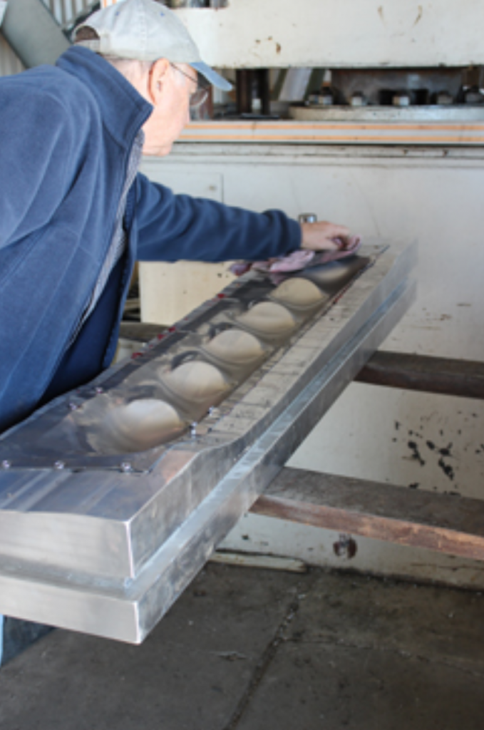
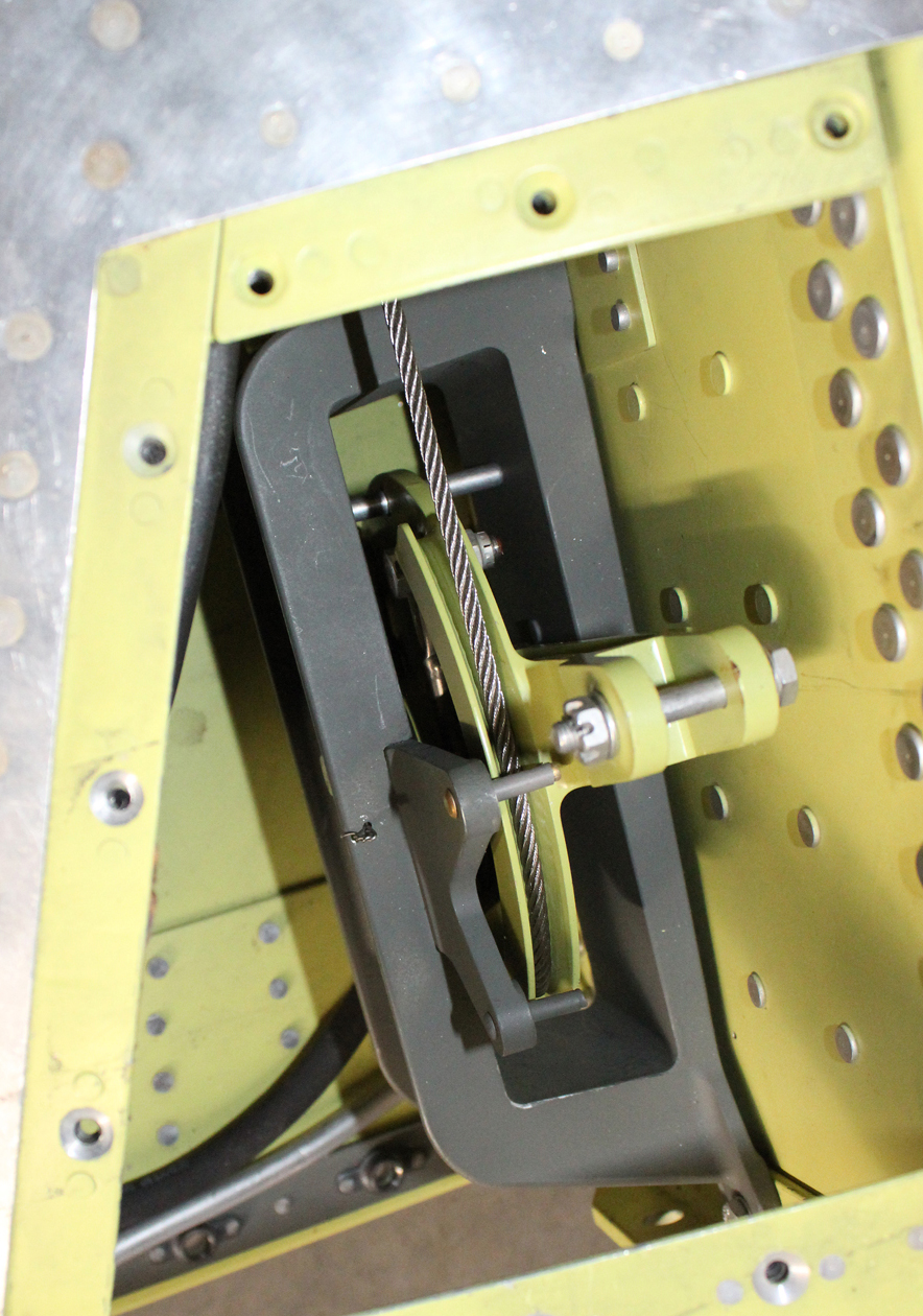
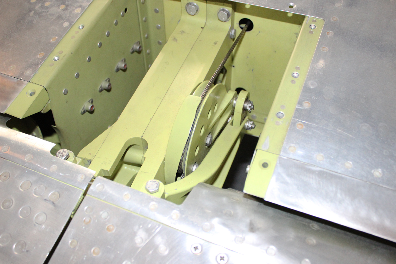
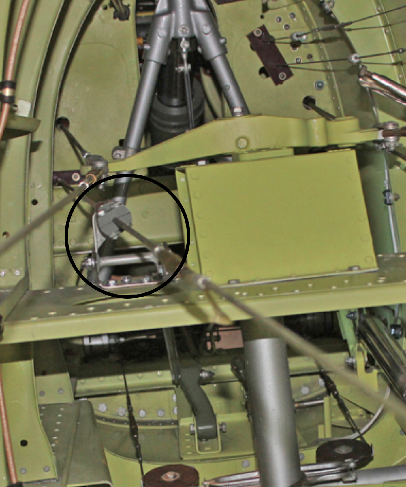
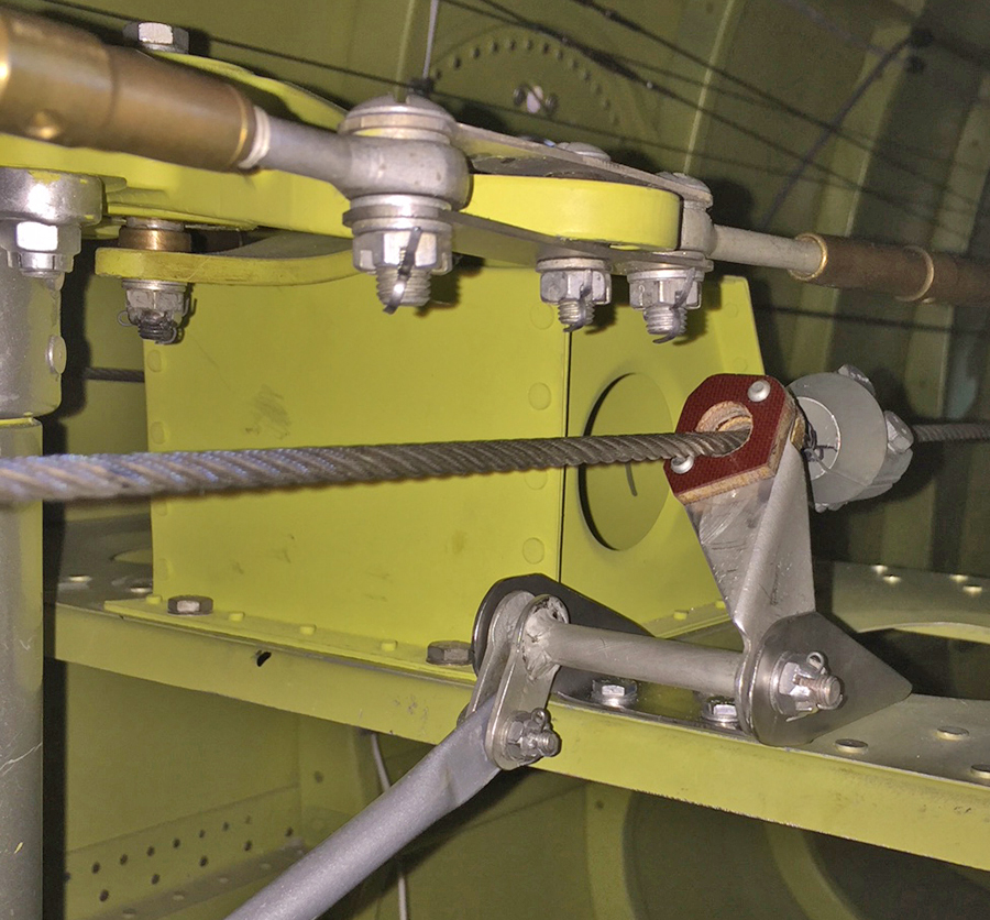
Carburetor Air Temperature Hot Air Door Controls:
Mounted in the back of each induction trunk is a door that opens to control the pilot-selected amount of carburetor heat (anti-icing) into each carburetor. Either pilot can adjust the position of these doors electrically from “closed,” to “half hot” to “full hot,” depending on the outside air temperature and humidity conditions during any point in the flight.
The hookup from the electric motor that rotates the air intake barrel back to the slide mechanisms, then down through two 90-degree arms, to a cable, then through a 90-degree pulley and back to the door arm was a difficult geometry puzzle to make them work on each induction trunk.
Inboard Gear Doors:
Both inboard gear doors are completely finished now, including painting the interior surfaces, and trimming. With new hinges attached, both of them are now fitted to the center section. Both doors have been hydraulically retracted, snapped into the hydraulically controlled up-lock latches and successfully released and extended numerous times.
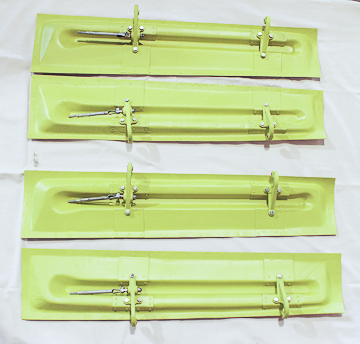
Tail Gear Doors:
All four tail gear doors are now completely finished, with their interiors painted. All eight hinges and four retract rods are attached, and the assemblies final fitted into each of the two tail wheel bays. Tom Riley and the team are awaiting two small brackets that mount on the two tail wheel lower arms that the pull/push rods attach to for retraction and extension.
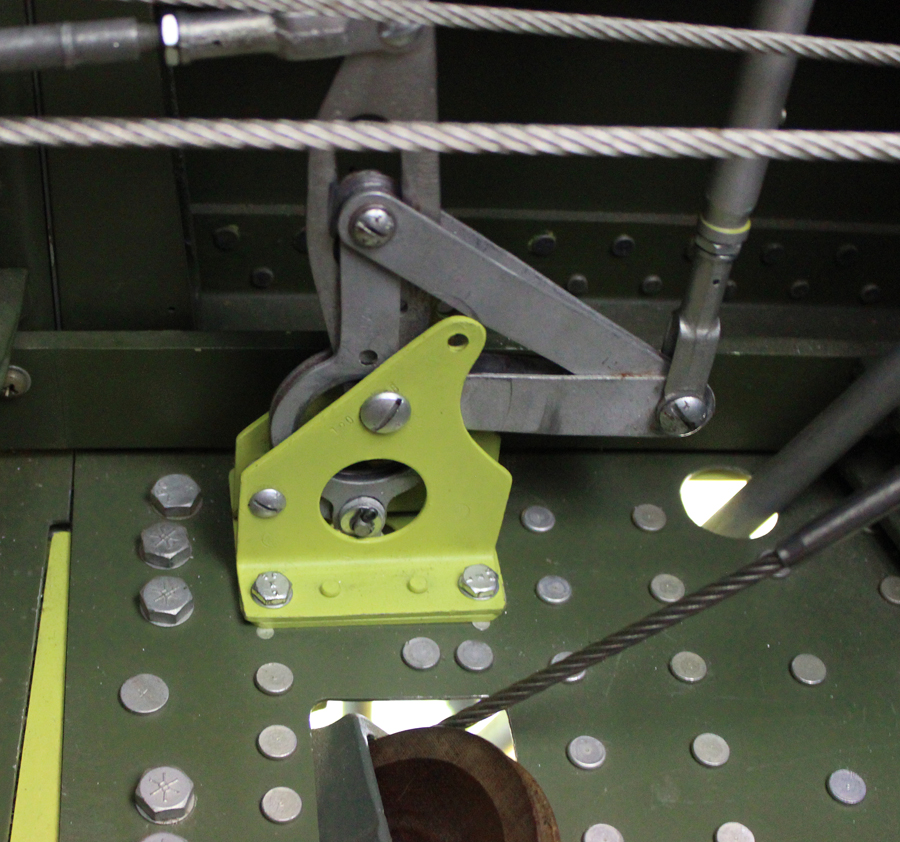
Aileron Bellcranks:
The team installed the aileron bellcrank boxes, one in each wing. These two boxes have a large cable sector with a lever arm that attaches to a push rod coming from the bottom of each stick. The movement of each synchronized stick (left or right) rotates the cable sector that has two cables attached to it that go out through the wing via two 90-degree pulleys and then back to another sector and arm that is attached to the ailerons.
Wings/Center Section Fuel Tank Testing:
The center section has two 95-gallon fuel tanks, one located underneath each cockpit floor outboard of each gun bay. Each outboard wing holds 205 gallons of fuel and has provisions for two drop-tanks holding a total of 450 gallons under each wing. Each drop tank has the ability to be air-pressurized from the vacuum pump discharge air through a cockpit selector to air-force the fuel back to the inboard center section 95-gallon tank. Total internal fuel capacity is 600 US gallons.
In December, the team completely filled all six tanks with fuel to test for leaks.
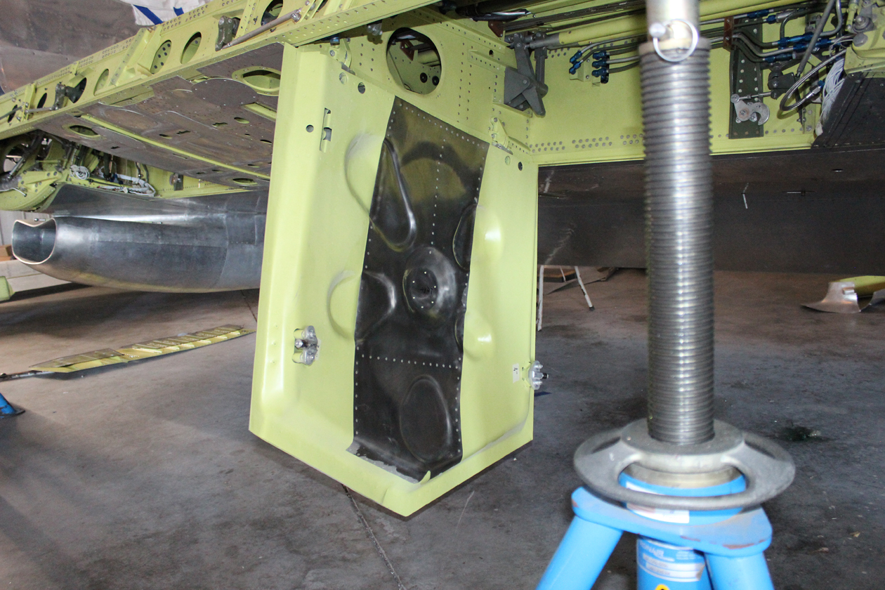
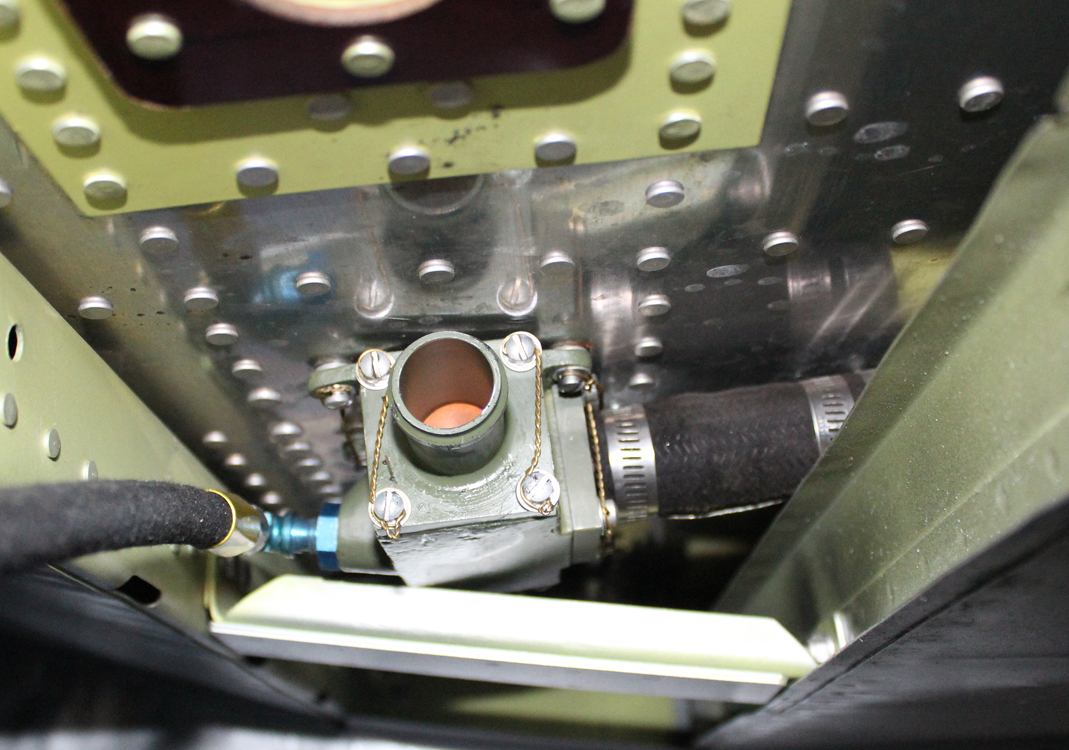
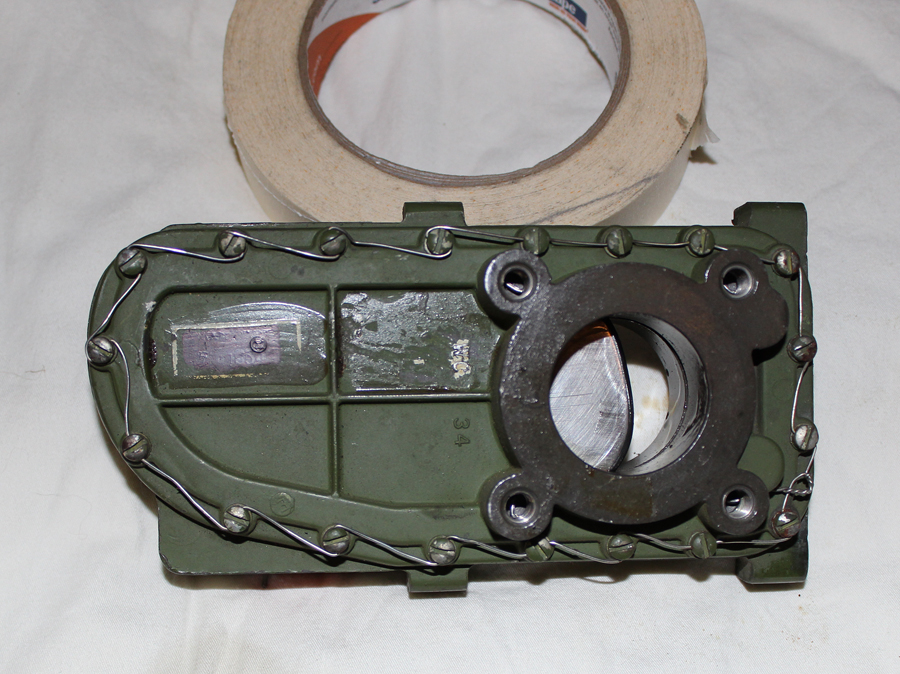
Cross-flow Check Valves:
There are two cross-flow check valves, one mounted above the belly scoop under each fuselage. These check valves control the fuel flow from the fuel tank boost pump located in each outboard wing and the fuel flow from the inboard 95-gallon tank boost pump to each engine. These valves prevent the outboard fuel being transferred to the inboard tank and vice versa. Boost pump fuel coming from either tank through the check valve housing will only go forward to the engine.
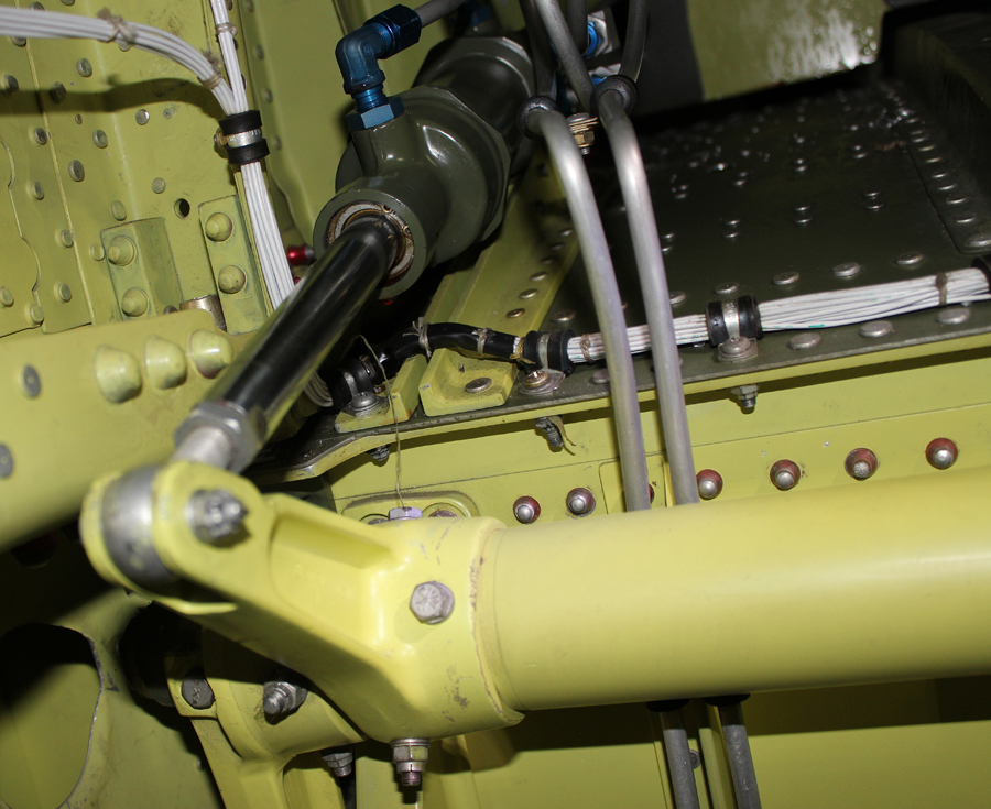
Fuel Shut-off/Cross-feed Valves:
These electronic shut-off and cross-feed valves have been final-tested and had the associated hoses attached. These valves are Whittaker guillotine-style valves that have a chrome-plated sliding plate that electro-mechanically opens and closes off each port.
Flaps:
The two flap hydraulic cylinders are now attached to the flap arms. The team hydraulically actuated them to test their functionality, and also adjusted the flap up-and-down stops accordingly.
Flap Follow Up Mechanism:
This mechanism is mounted on the left-hand cockpit floor underneath the flap actuator handle. It is a device that synchronizes the movement of the flap handle, the flap hydraulic actuator and the position of the three flap panels.
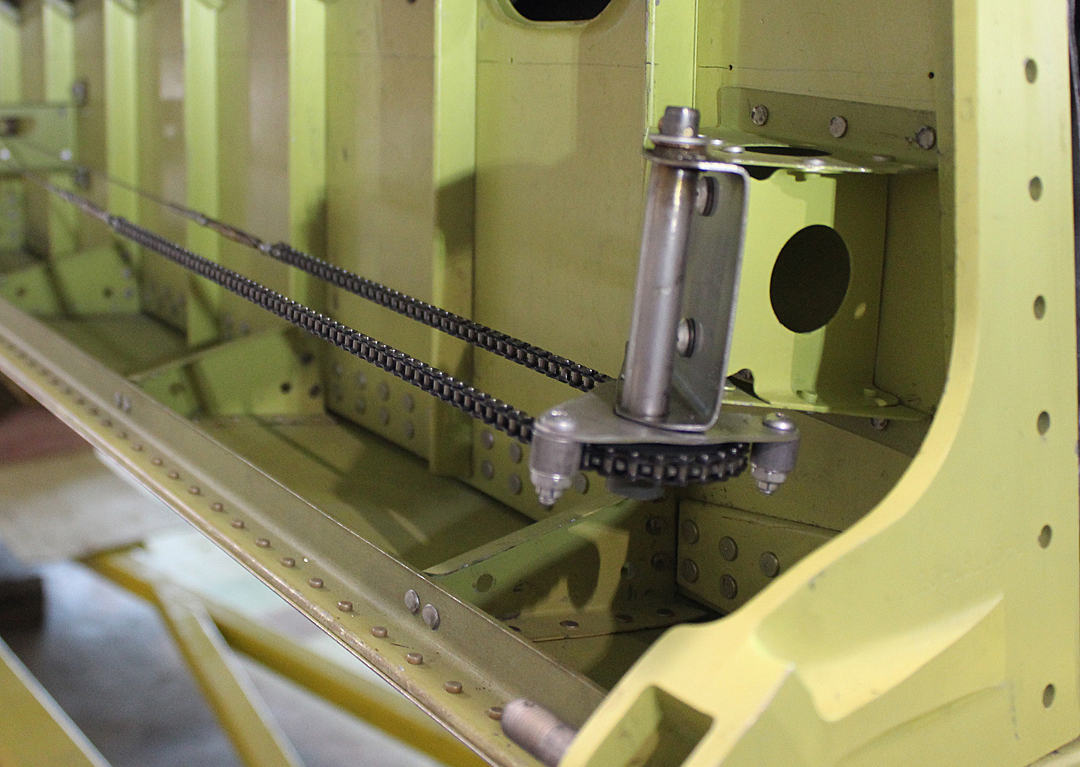
Aileron Trim:
The team has completed, installed and tested the aileron trim bellcrank and chain/cable mechanism.
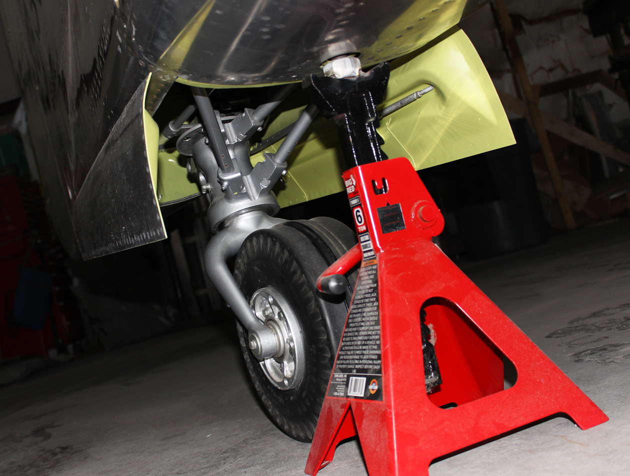
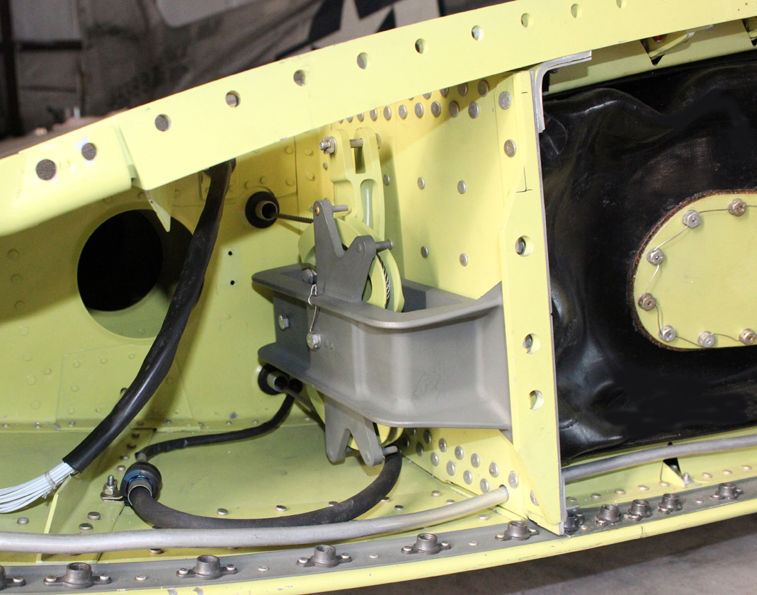
Tail Wheel Unlocks:
The restoration team was able to manufacture the two missing tail wheel steering unlocks. These unlocks release the tail wheel steering when either stick is pushed all the way forward. They are actuated by the down-elevator cable, one in each rear fuselage.
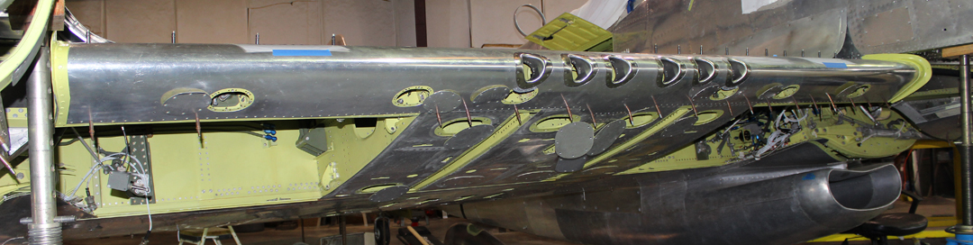
Leading Edge with Six .50 Caliber Gun Ports:
The center section leading edge has been left off in order for the restoration team to make the final adjustments on the gear door up-lock mechanisms. Now that these adjustments have been made, Tom Reilly has been final fitting the leading edge. Its installation will be completed by the end of next week.
And that is all for this month’s report.
Many thanks again to Tom Reilly for this update. You can learn more about the project on their blog HERE. Although we are not exactly sure when the next formal update will come, please be sure to check back with WarbirdsNews in a couple of months for the next installment in the story following the XP-82′s road to recovery!
Be the first to comment
Graphic Design, Branding and Aviation Art