

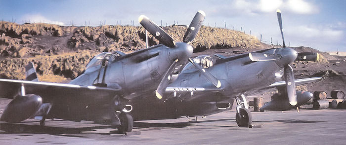
WarbirdsNews has received the latest XP-82 Twin Mustang restoration update from Tom Reilly at his workshop in Douglas, Georgia, and we thought you would all be pleased to see the latest progress!
Electrical
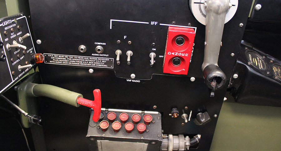
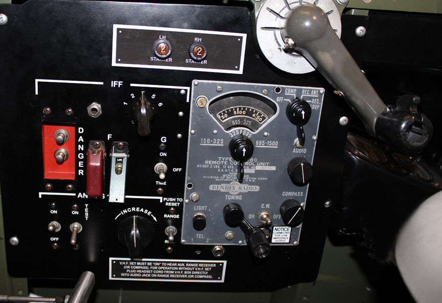
The restoration team is in the last phases of testing each electrical circuit. These are quite complicated systems in the XP-82 and also the first twenty B-model Twin Mustangs, which all had full dual controls. Each pilot had the ability to switch all electrical controls back and forth between each cockpit, i.e. boost pumps, fuel shut-offs, cross-feeds, all lighting, electronic mixture controls, coolant door motors, carburetor air temperature motors, generators, bombs, rockets, guns and superchargers. The transfer of electrical control was effected by selecting certain switching relays.
This unique ability to switch electrical control from pilot to co-pilot or vice versa was necessary because the Twin Mustang had a 12-hour plus range with external fuel. It allowed pilots to take turns resting on long missions. As an example of extreme endurance in a Twin Mustang, Col. Robert Thacker flew ‘Betty Jo’, a Merlin-powered P-82B, non-stop from Hickam Field, Hawaii to LaGuardia Airport, New York in 14.5 hours on February 27th, 1947. Thacker is still living today at the tender age of 100!
Tom Reilly finally found the last of the two electrical components necessary to complete the original radio installations. The impact detonator switches are now installed in both cockpits. These devices could be activated by either pilot prior to bailing out in order to ensure destruction of the then top secret IFF radios when the abandoned aircraft crashed.
Fuselage Fairings
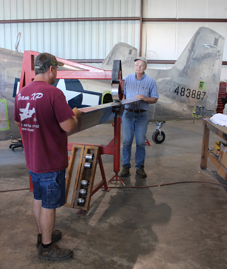
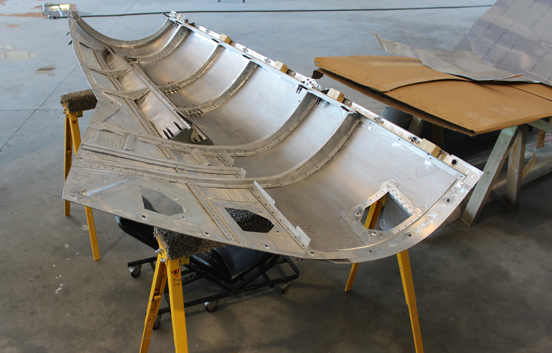
Most of the months of April and May have been spent English-wheeling skins for the fuselage-to-center section and fuselage-to-outboard wing trailing edge and wing fairings. Quite a number of complicated special curvatures had to be wheeled into the trailing edge fairings that do not show in the pictures. All four fairings are temporarily fit prior to final trimming.
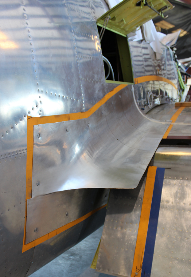
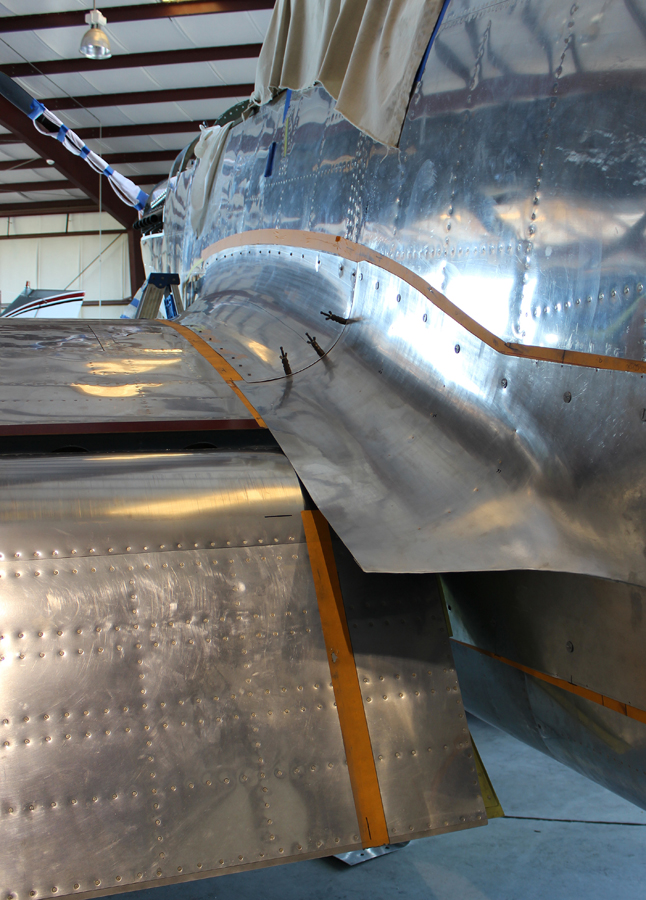
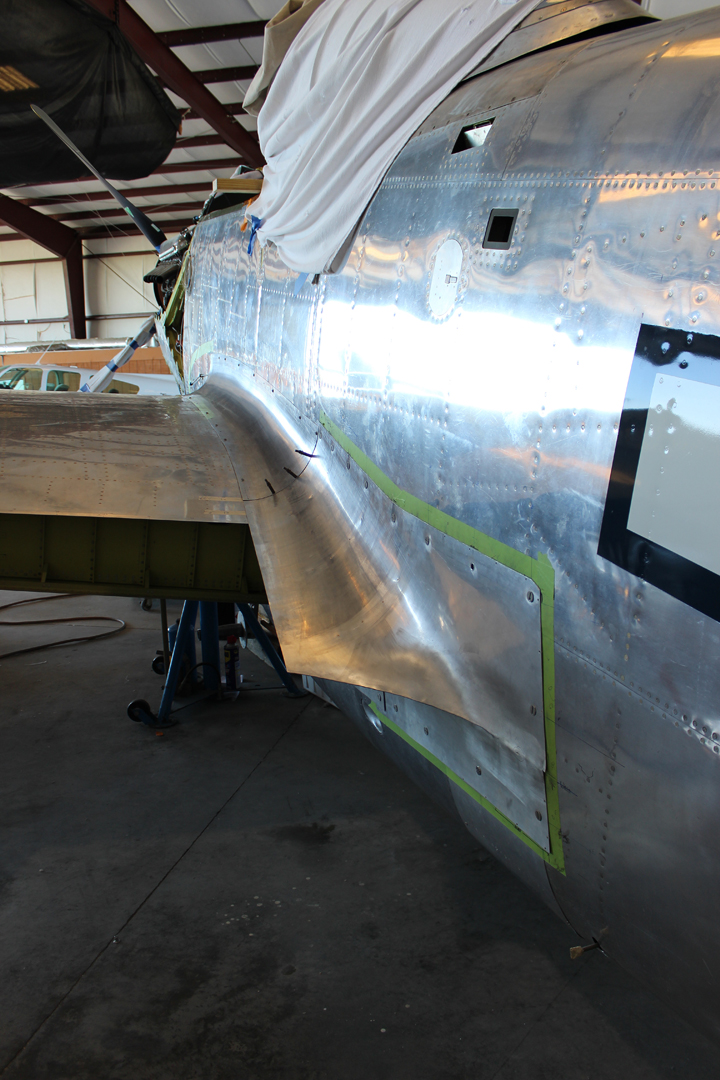
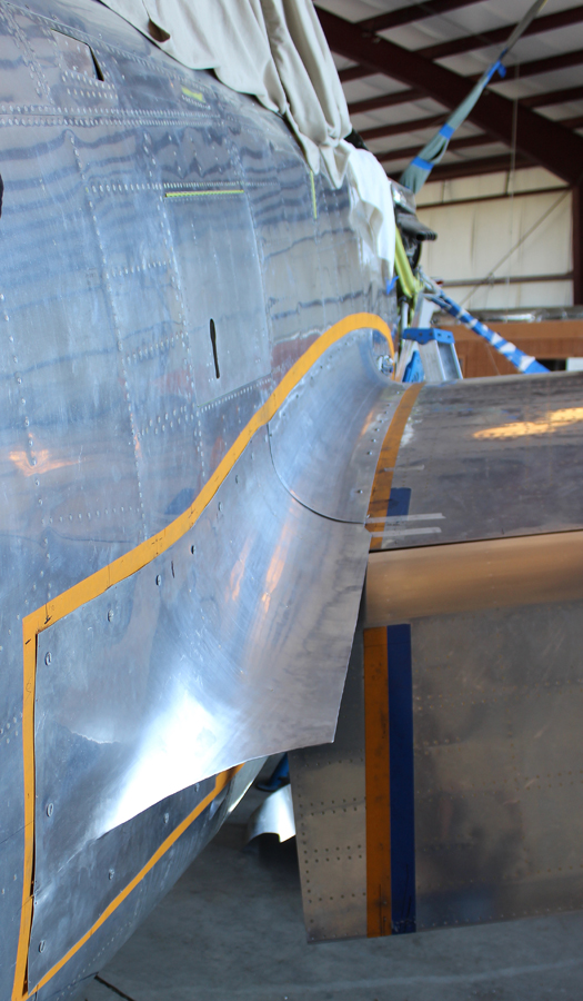
The team has just started forming the four compound curved leading edge fairings that go from the fuselages to the center section and fuselages to the outboard wings.
Top Engine Cowling
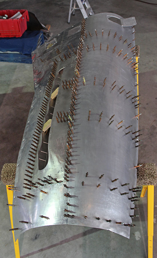
Prior to spot-welding, the tack riveting of the top right cowl for the right-hand engine is now being completed. The solid rectangular line of clecos shown in the picture is holding in the stainless exhaust trough. These will be filled with rivets as spot-welding will not attach stainless steel to aluminum. The opposing left-hand top cowling panel requires refabrication.
Hydraulic System
The hydraulic system tests for the landing gear and flaps should be completed by the end of June.
Control Systems
The final rigging of range movements for the primary flight control cables for both the elevator and rudders is now completed, along with their associated trim tab systems.
When the outboard wings are fully attached, the final rigging for the ailerons and trim tab will take place.
Firewall Forward
And that is all for this month’s report.
Many thanks again to Tom Reilly for this update. You can learn more about the project on their blog HERE. Please be sure to check back with WarbirdsNews in June, 2017 for the next installment in the story following the XP-82′s road to recovery!
Be the first to comment
Graphic Design, Branding and Aviation Art