Back in February, we reported on progress which the Commemorative Air Force’s Rocky Mountain Wing has made with the effort to return their TBM-3E Avenger (Bu.53503) back to airworthy condition following her engine problems last year. In February’s article, we showed the rebuild team re-installing the Wright R-2600 engine, which had just returned from overhaul at Anderson Aeromotive in Grangeville. For this article, the Rocky Mountain Wing’s Fred Suevel takes us through the process of re-installing the various engine ducting, along with the propeller, which has just undergone an inspection and Airworthiness Directive (AD) compliance with Westpac Aviation in Colorado Springs, Colorado. It is an arduous endeavor, and requires real dedication from all involved…
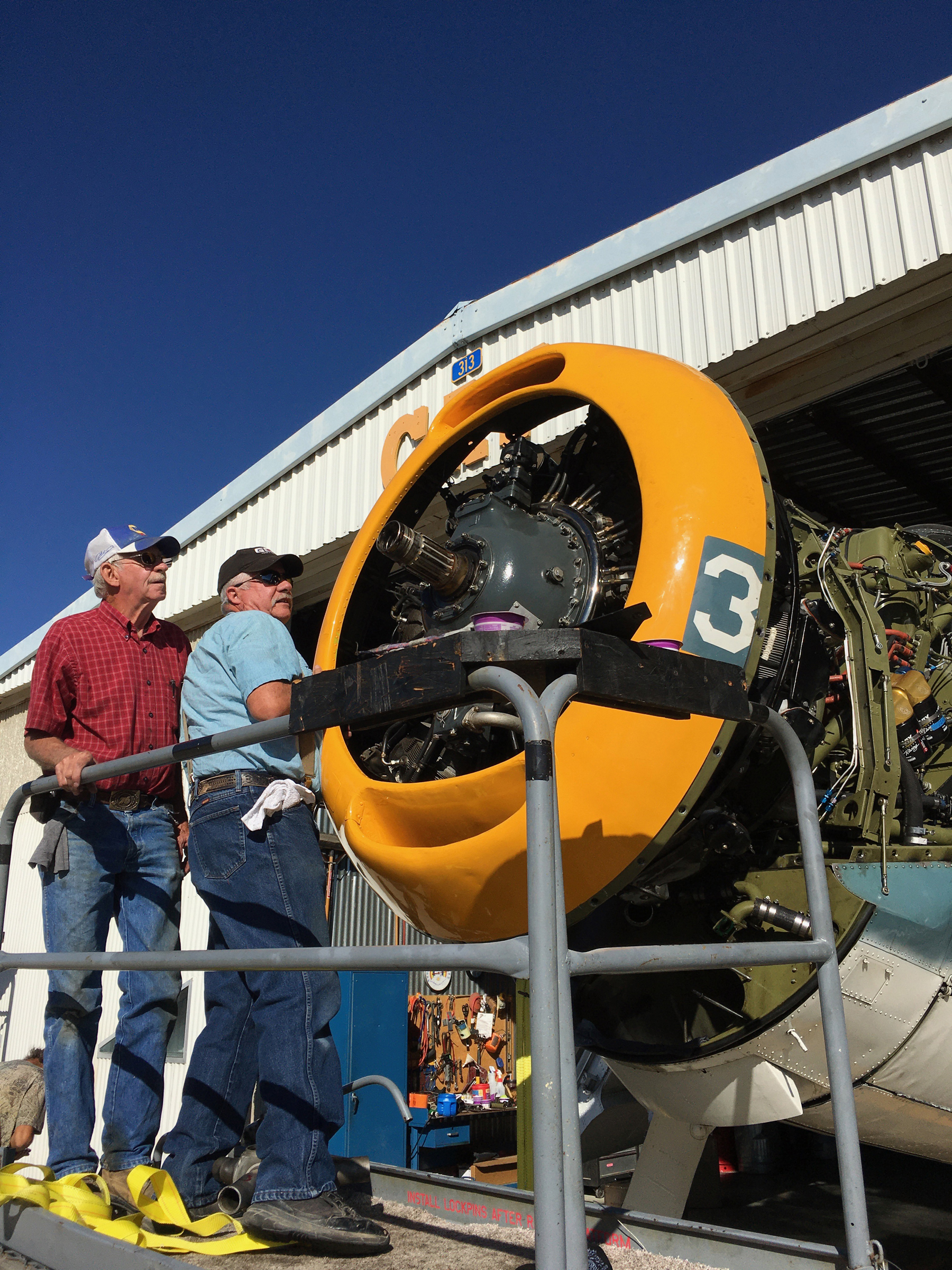
An image from July 16th, 2020 during the process of removing the engine for overhaul. It serves as a useful reference for following images. (image via Fred Seuvel)
The picture above was taken back on July 16th, 2020, when we took the engine off the plane for rebuild, but it’s a good reference for some of the following images. You’ll note at the top of the yellow nose cowling is an oval shaped opening. That’s the air intake for the engine. The next picture will show the air intake bridge which connects this opening across the top of the engine and into the curved air intake feeding the carburetor. This bridge also has the top skin of the plane over the engine.
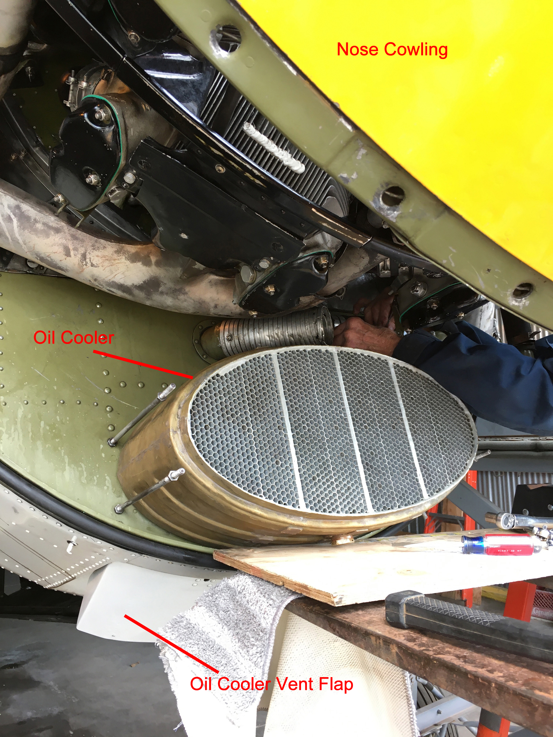
At the bottom of the nose cowling you can see another smile shaped opening. This feeds the air into the oil cooler. There is also, like the air intake bridge mentioned above, a piece which connects between the front cowling to the face of the oil cooler. You’ll see the oil cooler being installed in a subsequent image…
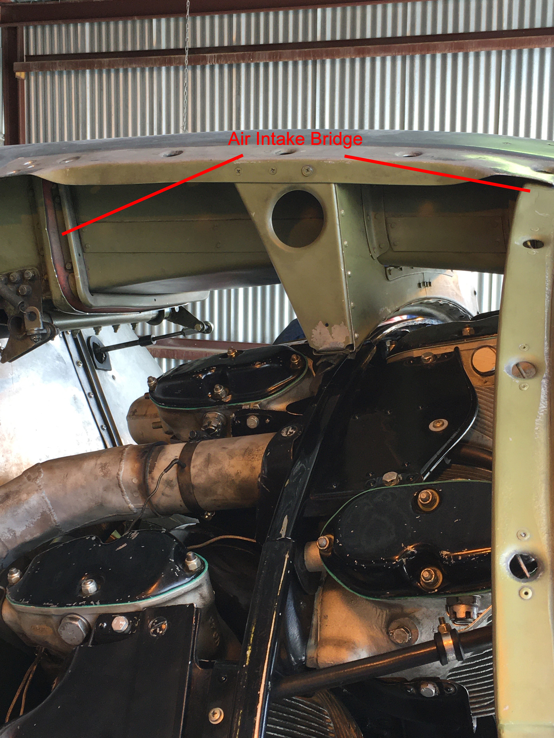
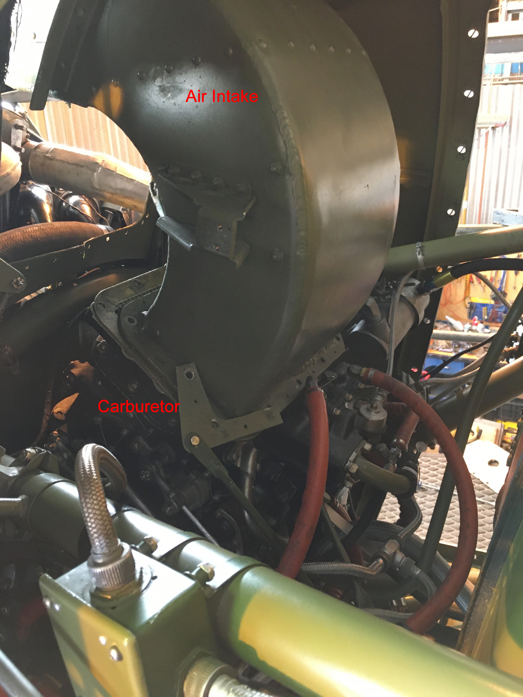
The Air Intake Bridge connected the top of the front nose cowling, just behind the propellor, to the air intake for the carburetor. (photo via Fred Suevel)
Dick is in the process of connecting the oil lines to the top of the oil cooler in this image. At this point the oil cooler has been pushed into an oval on the bulkhead which leads to a duct, on the other side of the bulk head, allowing the oil heated air to escape out of the bottom of the plane when the oil cooler vent flap is open as shown in this picture. There is an oval ring which mounts onto the front of the oil cooler, just over the edge of the honey comb cooling vents and onto four posts located two on each side. You can see three of the posts, two on this side and the bottom one on Dick’s side. His arm is covering the top post. (photo via Fred Suevel)
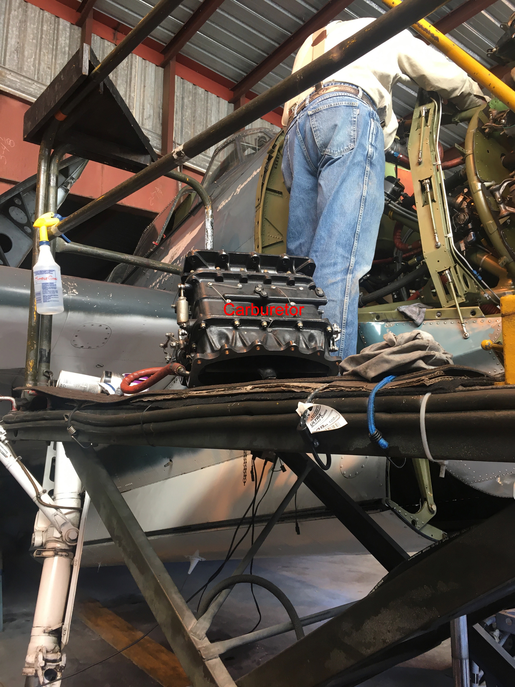
Byron is getting ready to install the carburetor on the engine. It is sitting on the lift in a position very close to the way it will be once installed. The carburetor will be placed on posts through the mounting flanges on the bottom. A curved washer and a nut will be placed on the posts to hold the carburetor in place. (image via Fred Suevel)
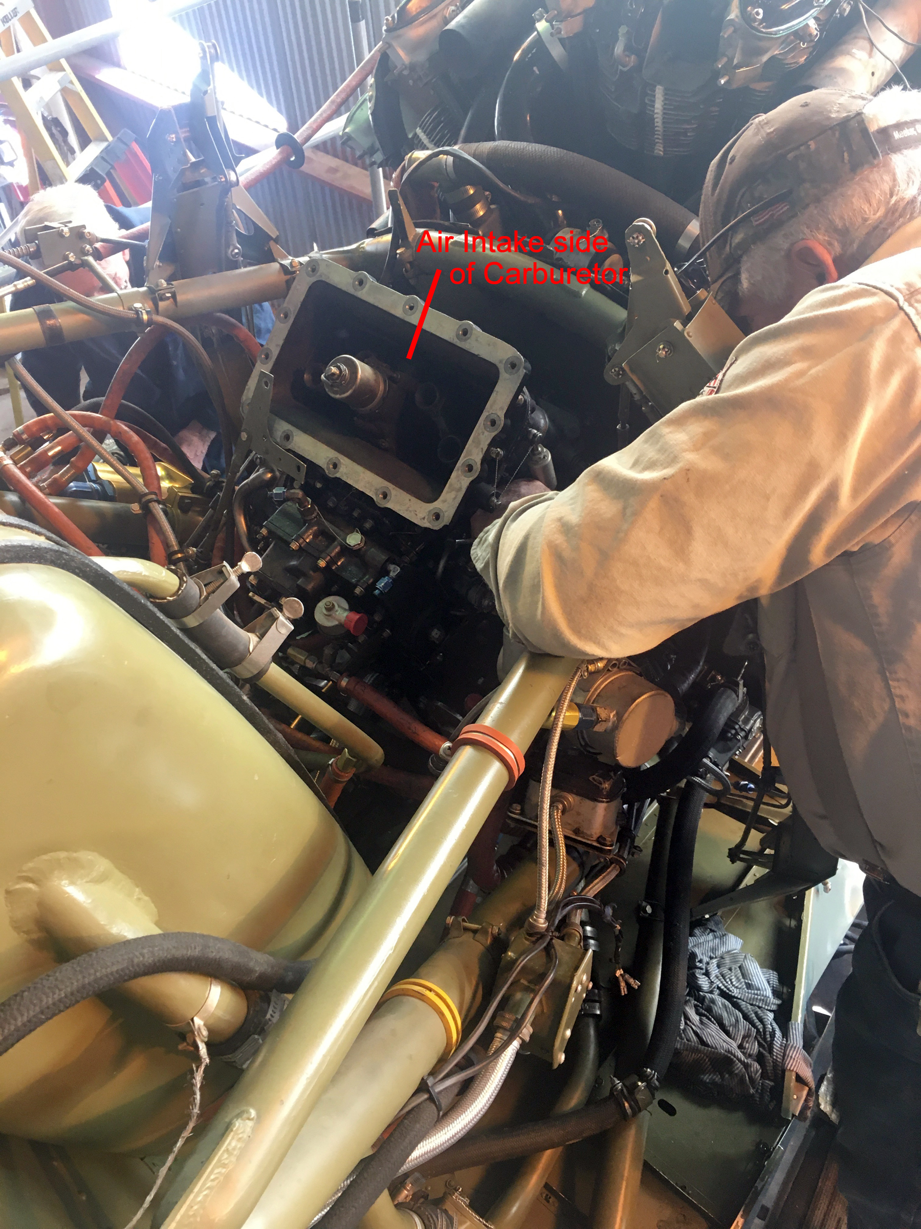
The Carburetor is in place and the nuts are being tightened. Byron is working on the close side and Dick is working on the far side. The nuts closest to the engine are a bear to get to, even with the special wrenches designed for this! Shortly after it was installed, we mounted a cardboard cover on the air intake to prevent anything accidentally falling into the carburetor. (image via Fred Suevel)
The carburetor now installed and protected (note cardboard cover in place), Dick moves onto the propellor pitch control cable which goes through the left side firewall. (image via Fred Suevel)
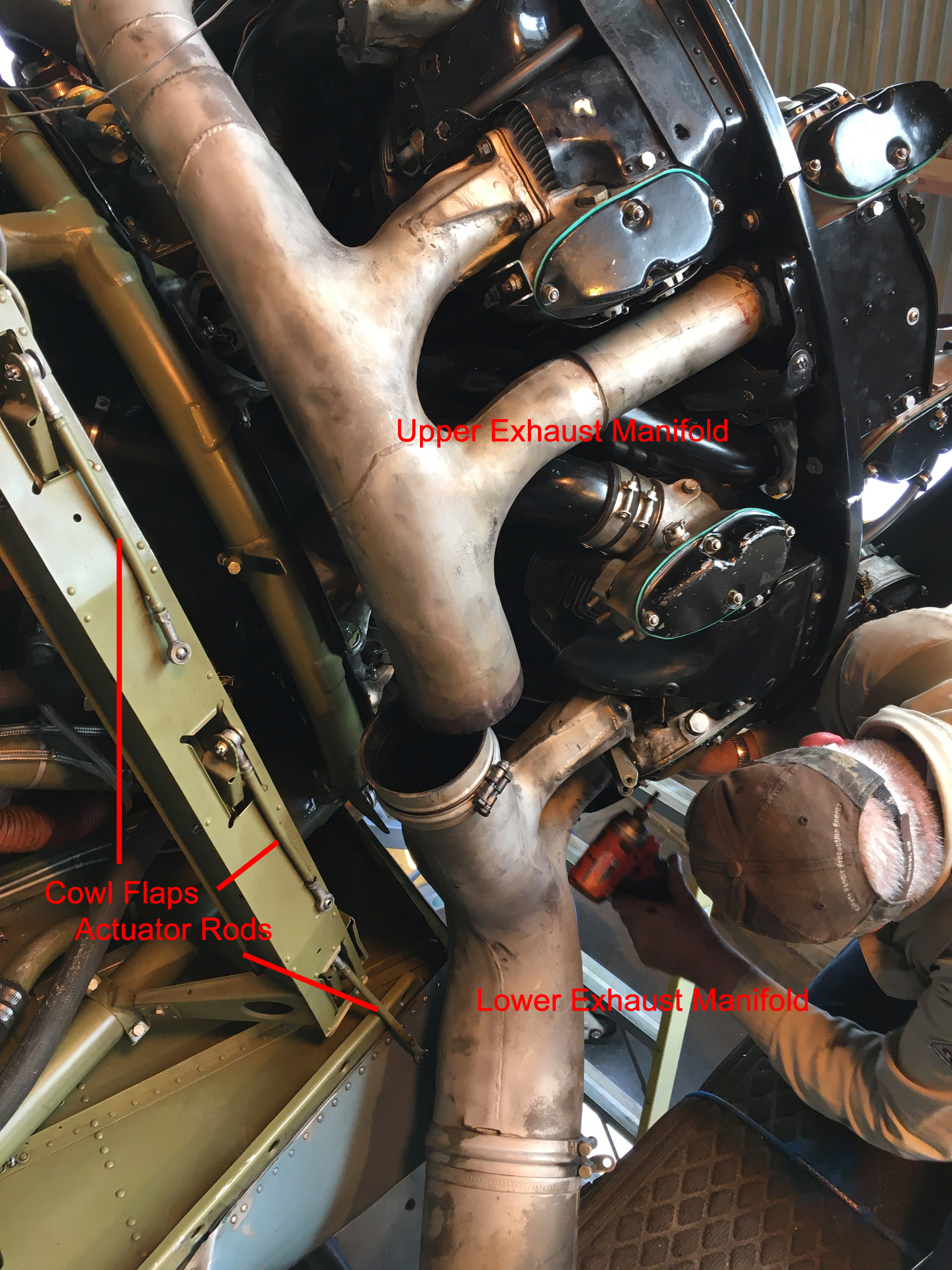
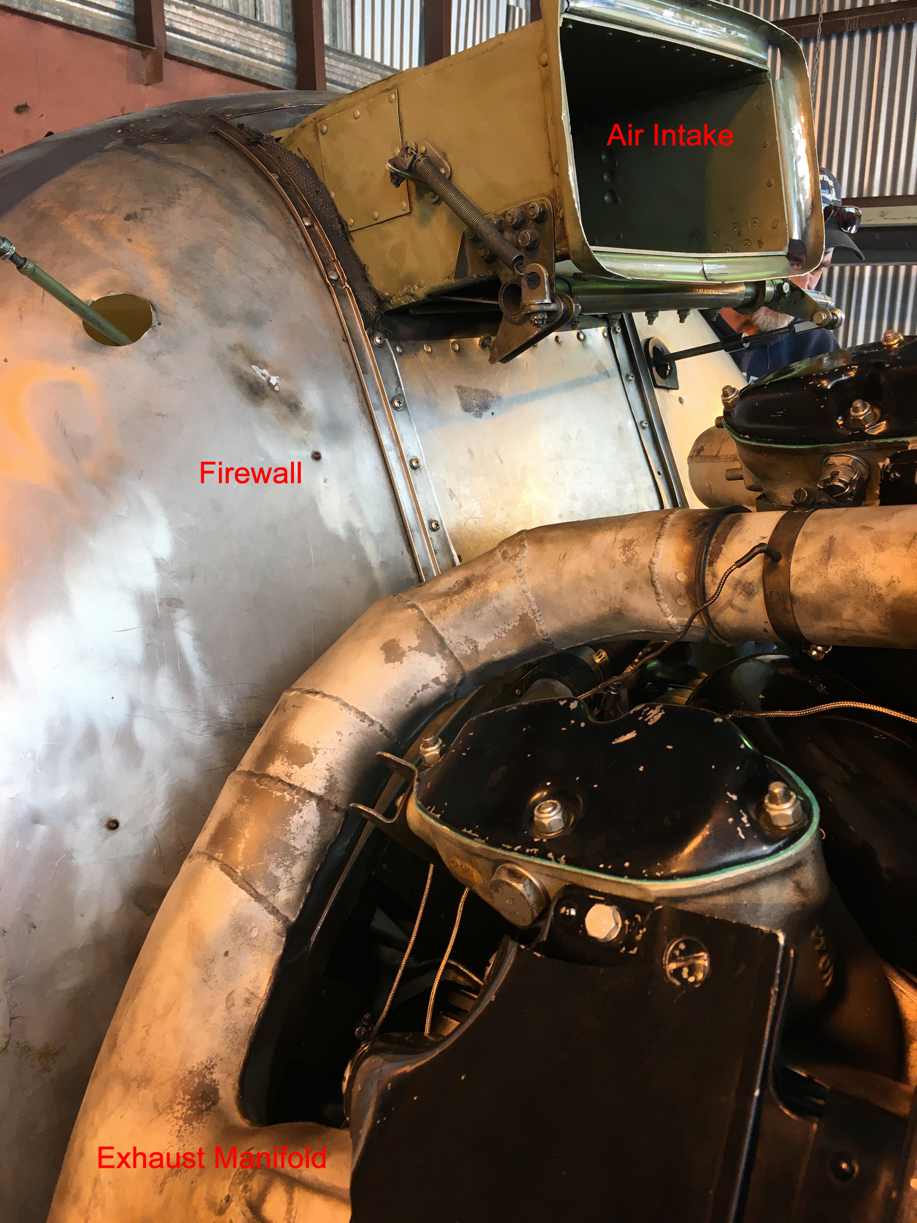
The exhaust manifold breaks down into four pieces plus seven extension pipes to reach the front cylinders. The front pipes are installed loosely first. Then the upper manifold is pushed into place and again loosely bolted in place. The lower manifold is then put in place and, finally, the upper and lower pieces are pushed together. The last part is to go back and properly torque each of the nuts holding the exhaust manifold onto the engine. In this picture you can also see the actuator rods for right side cowl flaps. (image via Fred Suevel)
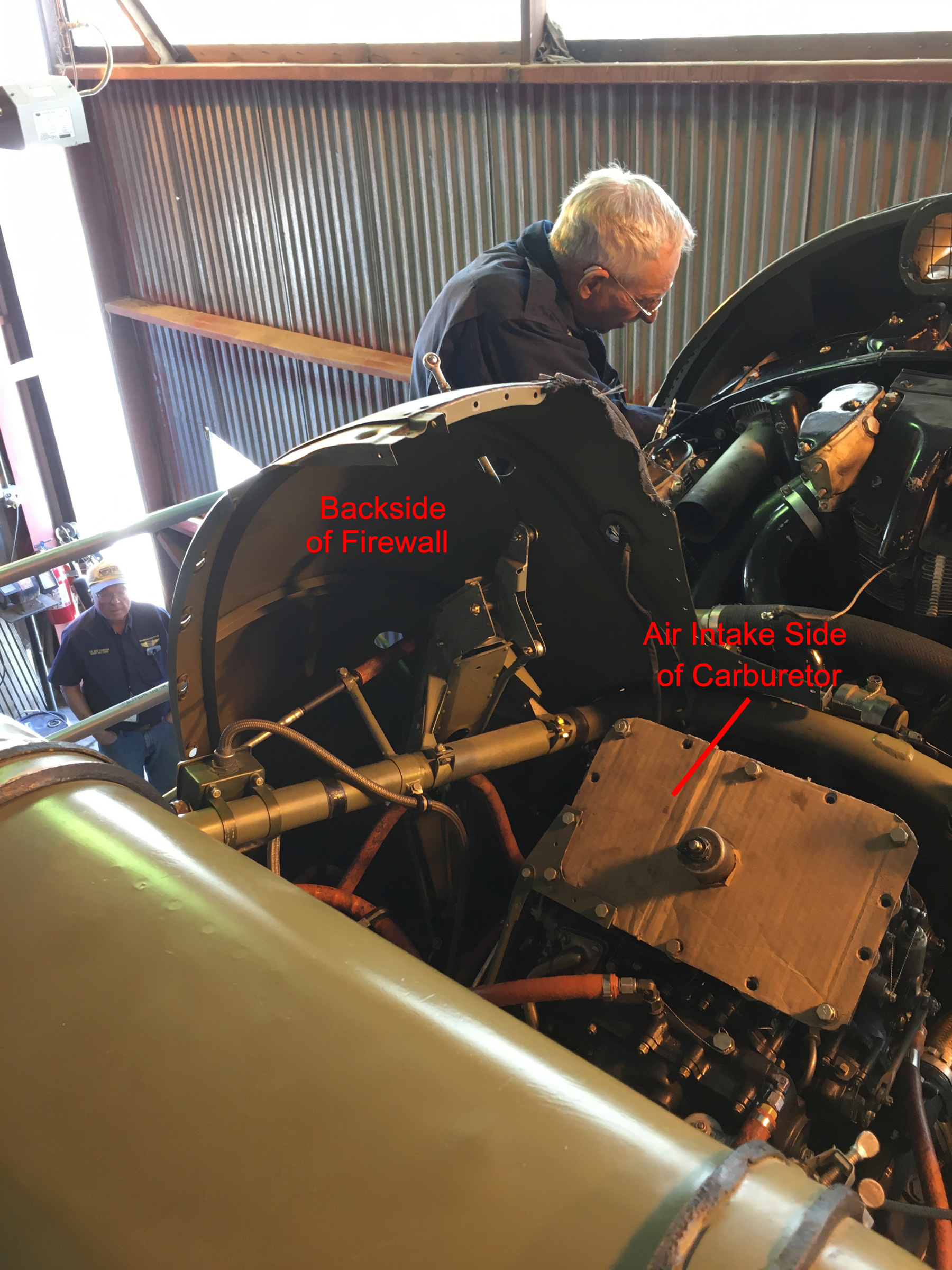
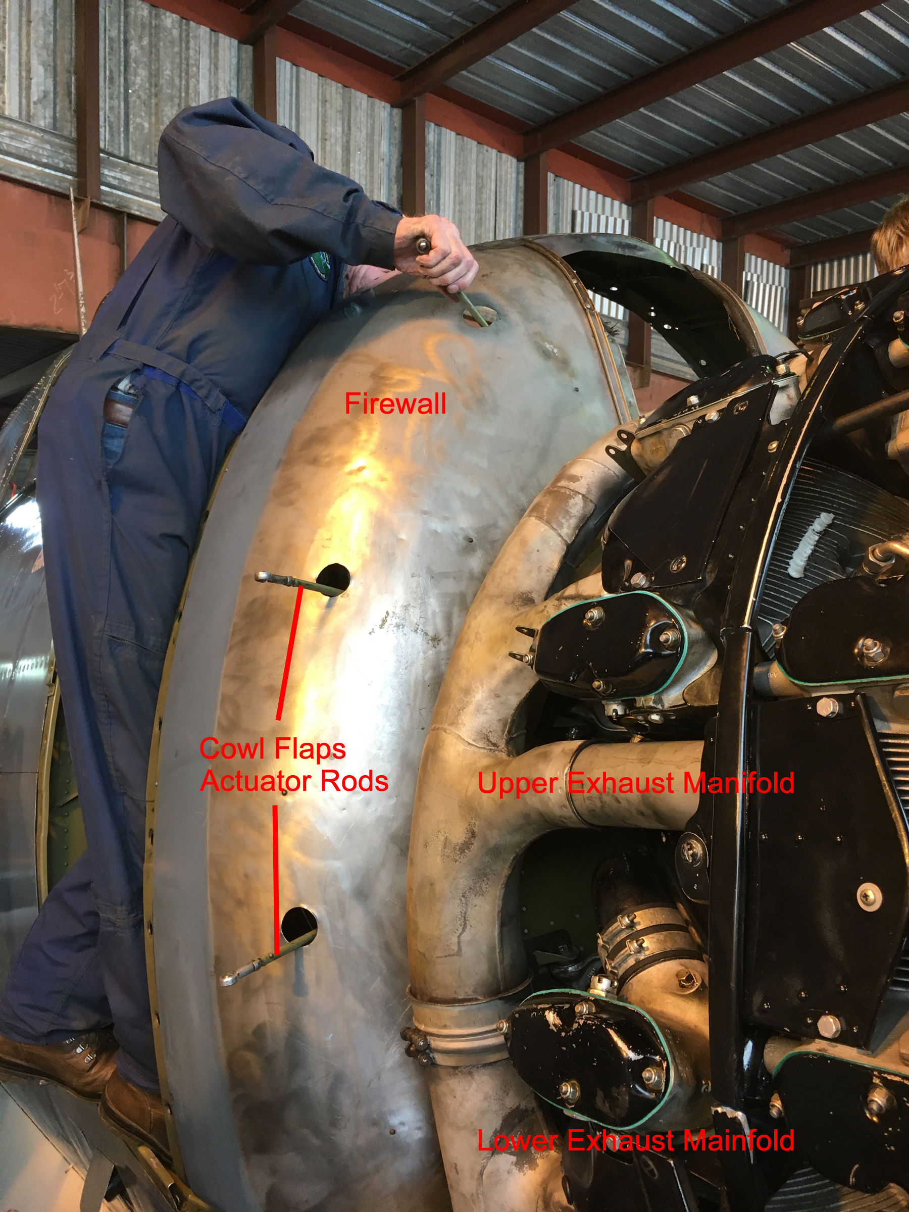
The next step is to install the firewall between the hot engine parts and the accessory bay. The cowl flap actuator rods come though the firewall getting ready to connect with the cowl flaps. On the back side of the firewall is the generator, oil pump, fuel pump, hydraulic pump, vacuum pump, oil filters and oil tank. The opening on the firewall is where the air intake will come to the carburetor from the nose of the plane. (image via Fred Suevel)
From the backside of the firewall, you can see the air intake sitting on top of the carburetor getting ready to be bolted into place. (image via Fred Suevel)
The air intake is now installed and the area below the intake is filled with a flat piece of aluminum to complete the sealing of the engine from the accessory area. There is another piece of rectangular pipe which goes from the front cowling to inside the flanged area of the air intake. (image via Fred Suevel)
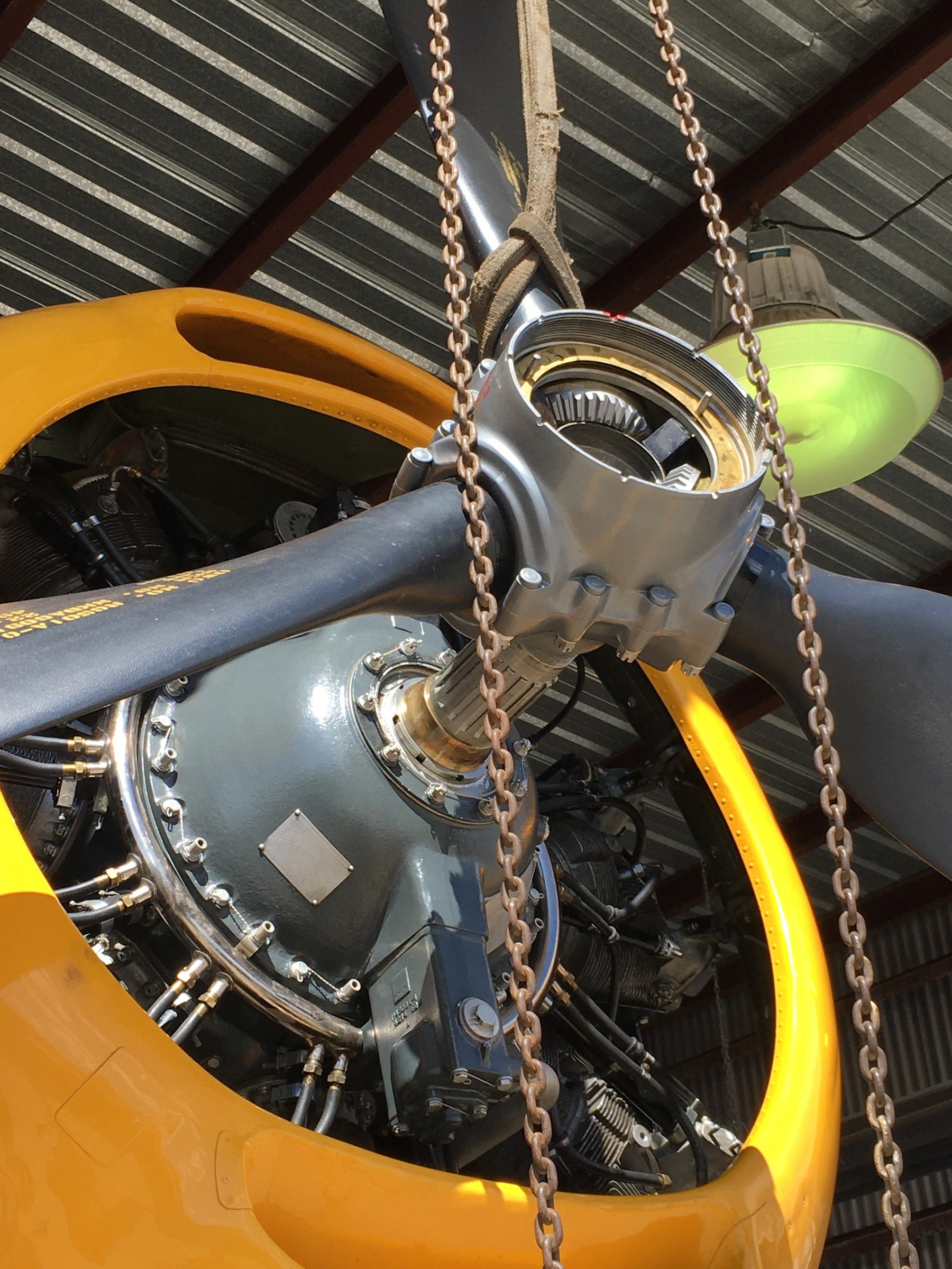
And now we come to the propeller installation. The unit returned from Westpac a few days ago, and the Rocky Mountain Wing soon got to work re-installing the massive 13 foot 1 inch diameter unit.
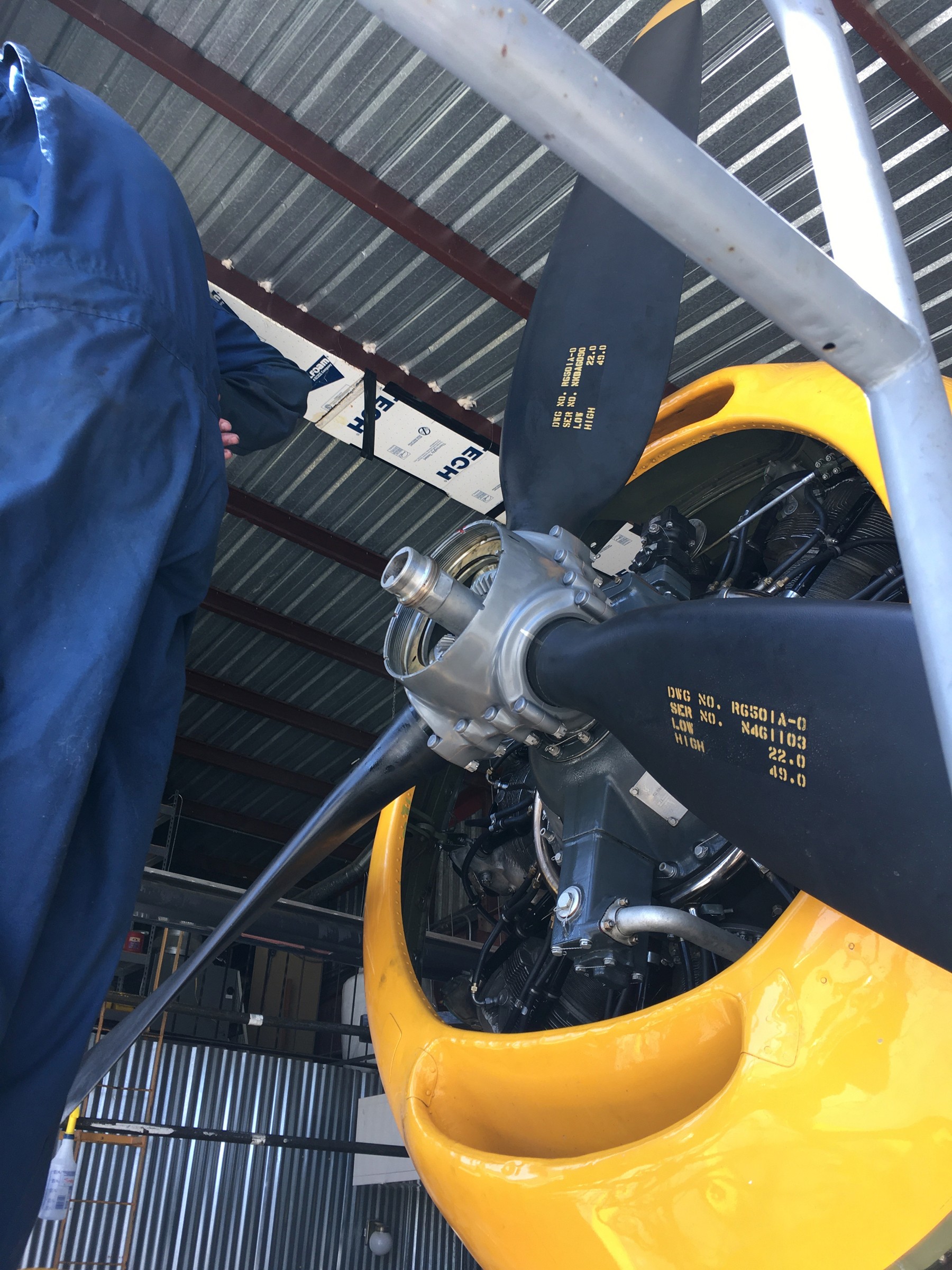
The propeller suspended on an overhead winch is moved into position in front of the drive shaft. The splines on the drive shaft will be aligned with teeth in the center of the propeller hub. (photo via Fred Suevel)
Dick and Byron are aligning the hub splines with the shaft teeth. Once aligned they pushed the propeller onto the shaft. (photo via Fred Suevel)
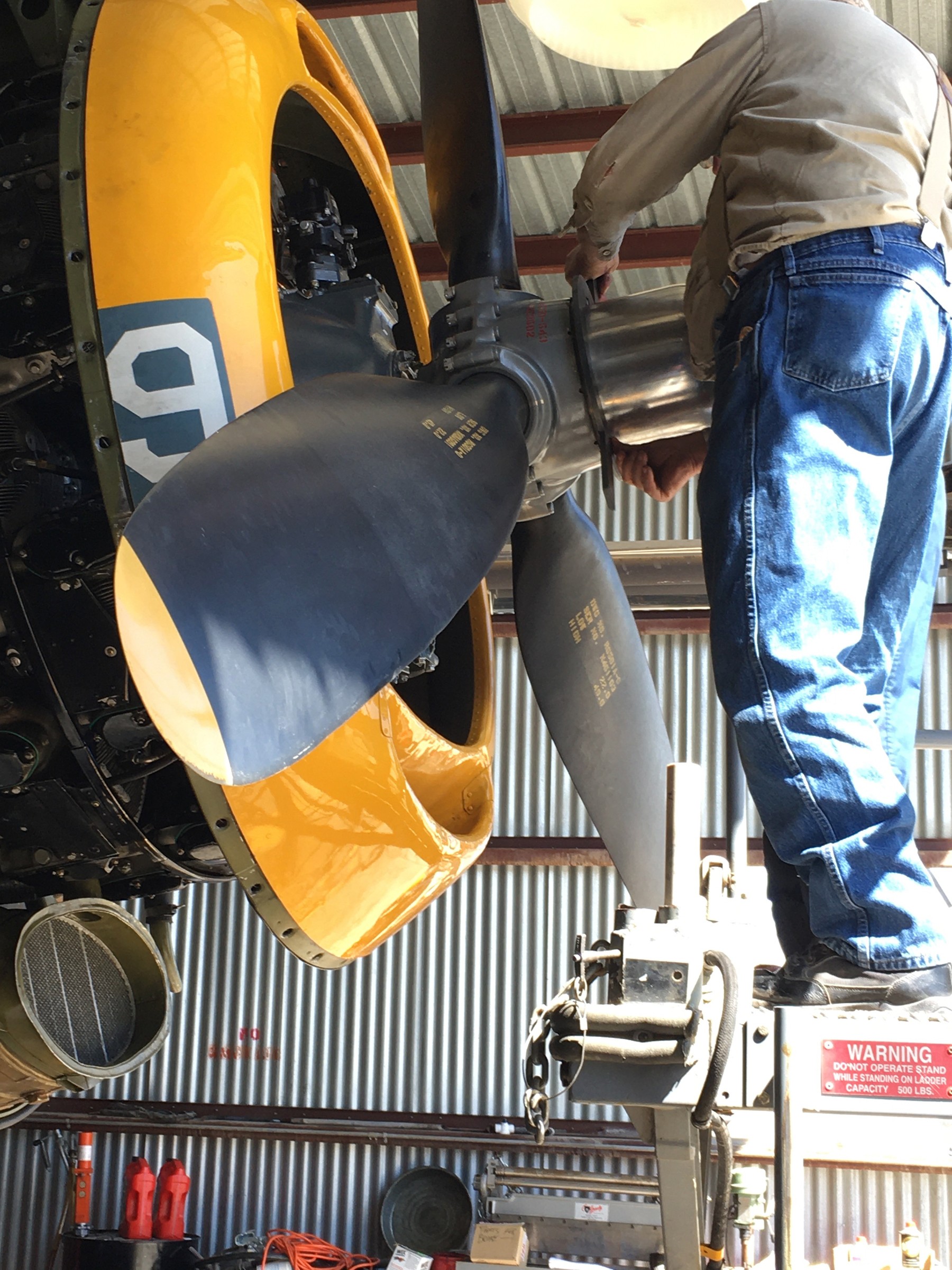
The propeller is now properly sitting on the shaft. The next part is the dome. Inside the dome are gears which will mesh with the individual propellor gears which can be seen in the hub. These gears control the pitch of the propellors. They are driven by high pressure oil inside the dome. (photo via Fred Suevel)
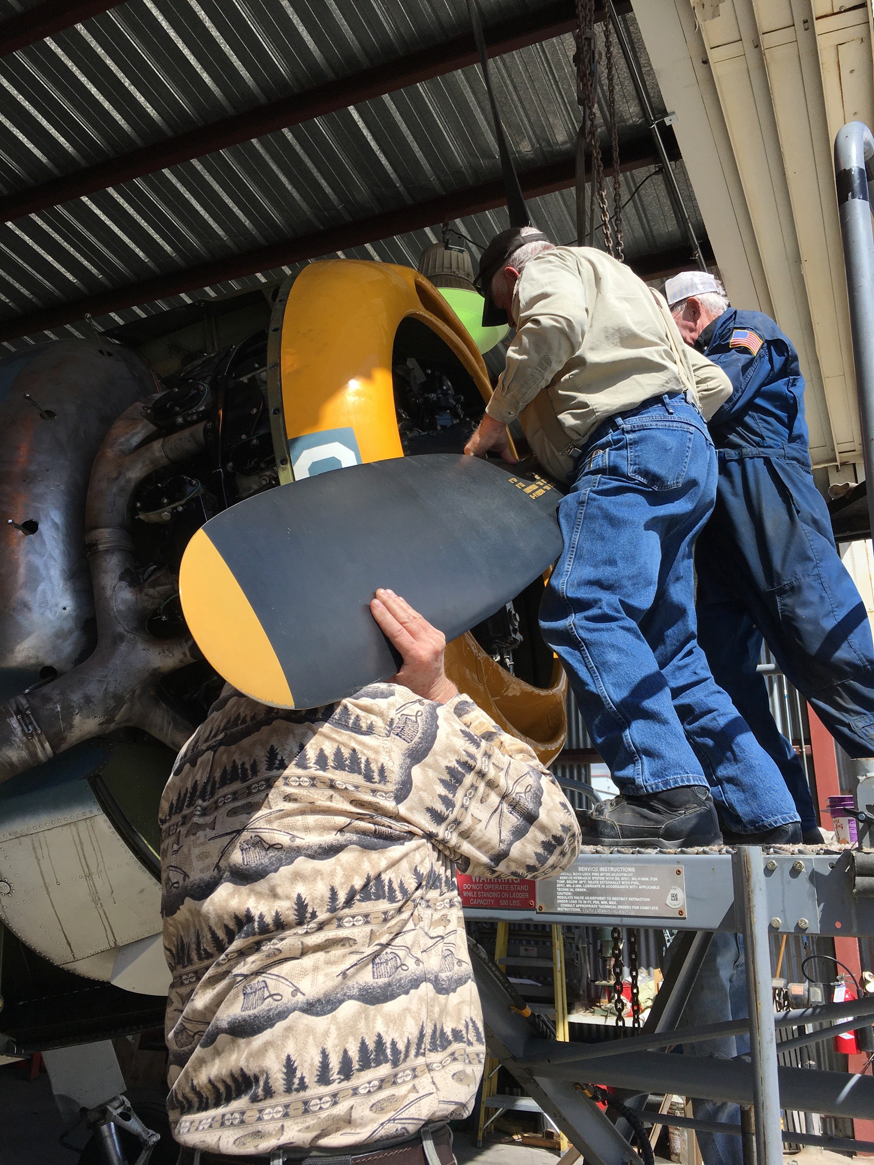
The dome has been installed and Byron, using a special wrench, is tightening a very large lock nut to hold the dome on the hub. (photo via Fred Suevel)
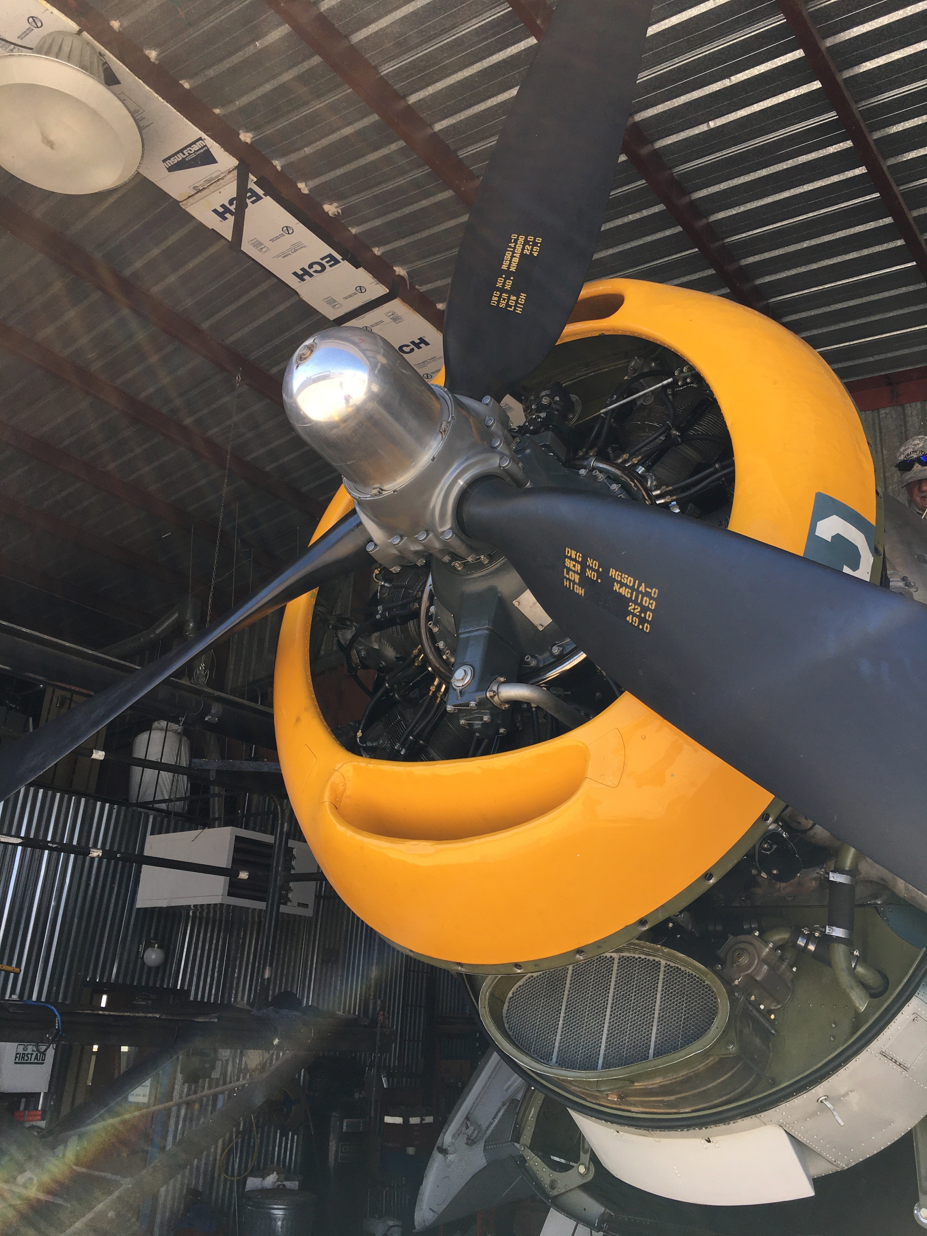
The propeller is finally installed. At the bottom of the dome, you can see a small tab that appears to be coming out of the hub. There is also one at about the 90 degree which is harder to see. These are two of four tabs which lock into that special wrench used to tighten the lock nut holding the dome in place. (photo via Fred Suevel)
And that’s all for now from the Rocky Mountain Wing… We thank them greatly, especially Fred Suevel and Kevin McNulty, for sending us these fascinating, detailed images describing just a small aspect of the hard work which goes into maintaining one of these precious vintage aircraft. We hope you’ve enjoyed seeing a little of what it takes to “keep ’em flying!”
For those wanting help the Rocky Mountain Wing maintain this magnificent aircraft, please click HERE to contribute… no amount is too small, and we all thank you for your help!


Be the first to comment
Graphic Design, Branding and Aviation Art